Motivation: Why Datums?
If you actually read ASME Y14.5-2009, the first important point made relates to the foundational concept of the datum reference frame.
When applying GD&T the first consideration is to establish a datum reference frame based on the function of the part in the assembly with its mating parts.
In this article, we’re going to focus on all things datum related in GD&T. Without a solid understanding of datums you won’t have the ability to construct feature controls that communicate your design intent. We’ll start by going over some of the basic terminology and definitions related to datums. Then we’ll use real part and assembly examples to demonstrate how to select the right datum features on your part to build a datum reference frame that communicates design intent and makes inspection setup simple and accurate.
Basic Terminology and Definitions
GD&T terminology can get tricky so let’s start with a few key definitions: datums, datum features, and the datum reference frame.
-
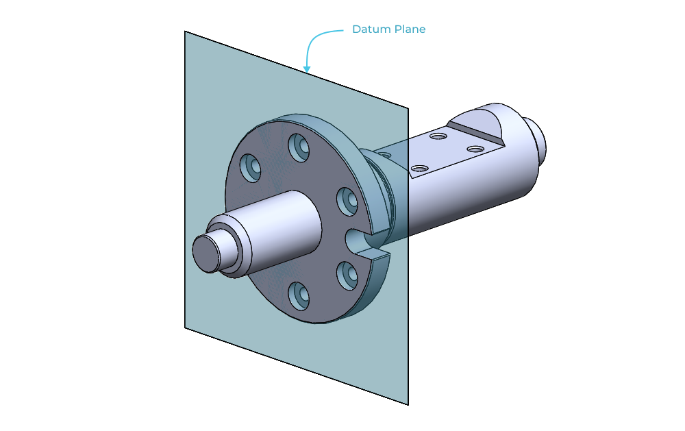
Datum: ASME Y14.5 defines a datum as a theoretically exact point, axis, line, plane, or combination thereof derived from the theoretical datum feature simulator. Putting aside the definition of the theoretical datum feature simulator for now, the important thing to remember is that datums are theoretically exact.
-
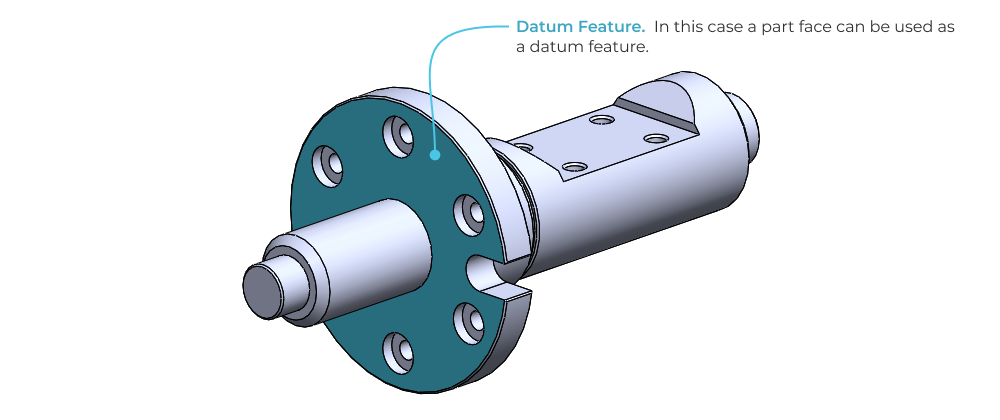
Datum Feature: A datum feature is a feature that is identified with either a datum feature symbol or a datum target symbol. In this case we’re talking about actual part features; things like faces, edges and vertices. For now don’t worry about feature and target symbols, just know that datum features are associated with real parts and are not theoretical.
-
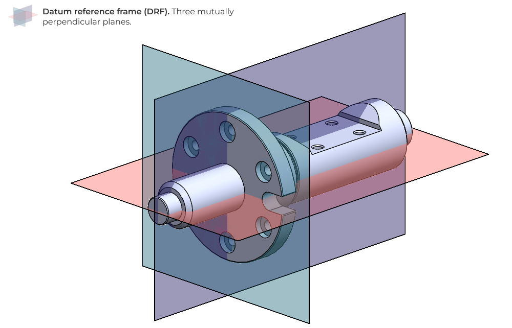
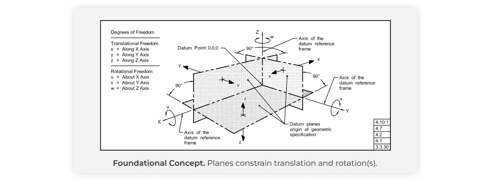
Datum reference frame (DRF): A datum reference frame is three mutually perpendicular intersecting datum planes. The datum reference frame establishes a shared set of orthogonal planes that is leveraged by all subsequent feature controls and tolerances that you specify. Without a properly constructed DRF, your feature controls may not communicate your design intent.
Importance of the datum reference frame (DRF)
Returning to the first consideration in GD&T we know that we need to establish a datum reference frame based on the function of the part in the assembly with it’s mating parts. But why?
Purpose of the DRF
The DRF is a coordinate system that is used to establish the size, shape, orientation, and location of a part and it’s constituent features. It provides a common reference point for all dimensions and tolerances specified on the part, allowing engineers and manufacturers to consistently interpret and apply the GD&T symbols and tolerances.
Practically speaking the DRF is the nominal (or theoretically perfect) reference for every controlled feature on the part. For example, if you were drilling a deep hole through the center of a shaft and you want the hole to be concentric with the shaft itself, you need to establish a perfect representation of the shaft’s axis. The DRF embodies this perfect representation through the construction of three mutually perpendicular planes.
Building a DRF by selecting datum features
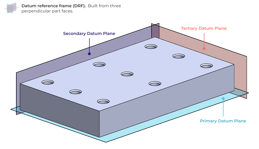
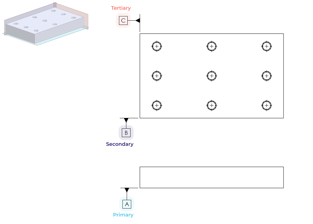
A DRF is composed of three datums: primary, secondary and tertiary datum planes. These datums are defined by selecting datum features on the part (note: the datum features do not necessarily have to be planes themselves). The simplest possible DRF is defined by three orthogonal part faces, as shown on the prismatic part below.
Here’s how the selected datum features would appear on a drawing of this example part.
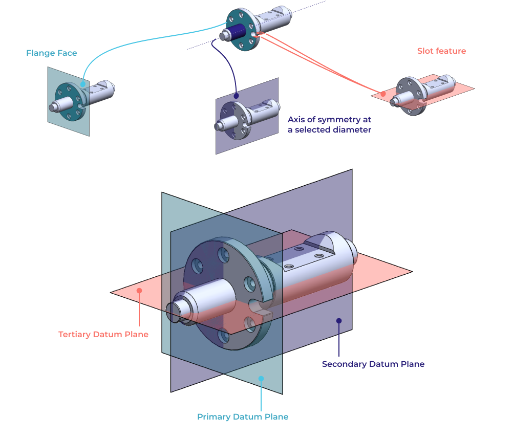
It's important to remember that the selected datum features don’t have to be faces however, they can also be points, axes, center planes, and more. To demonstrate this we can continue with the example part used in the definitions section of this article. In this case, due to the non-prismatic nature of the part, it’s not as clear how we can define a functional DRF.

In this case we can use the flange face with the counterbores as the primary datum plane. Then we can use the rotational axis of symmetry as a datum axis, combined with the slot feature to establish a datum plane that clocks the rotation of the part. The selected datum features and associated DRF are shown below.
DRFs and constraining the part with the 3-2-1 rule
The sequence of datum features that you choose directly relates the part to the DRF. The order is important because it establishes how the degrees of freedom of the part are physically constrained (this matters for part inspection).
We’ll demonstrate this by using the 3-2-1 rule to build a DRF on a simple rectangular part. The 3-2-1 rule defines the number of points of contact required to define primary, secondary and tertiary datum planes.
3-2-1 Rule
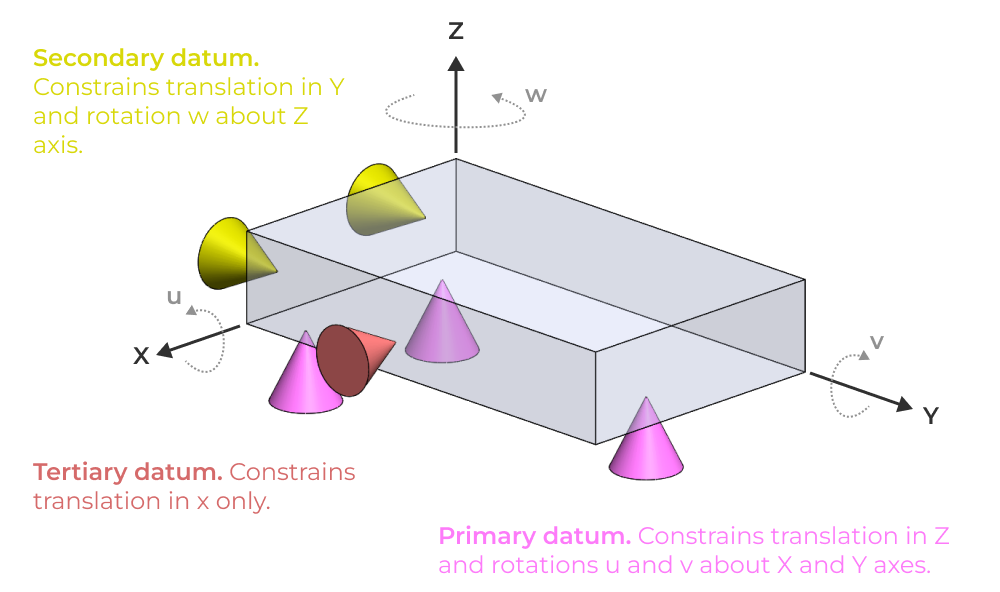
- Select a primary datum feature. Usually this is a functionally important face, often one that mates directly with other components. The primary datum feature must have at least 3 points of contact with its datum plane. This restricts two rotational degrees of freedom (DOF) and one translation DOF.
- Select a secondary datum feature. The secondary datum feature must have at least 2 points of contact with its datum plane. This restricts an additional two DOF, one rotation and one translation.
- Finally, the tertiary datum feature has at least 1 point of contact with its datum plane. This restricts the last remaining translational DOF (of 6 total). Now the part is fully constrained.
Defining DRFs by selecting datum features
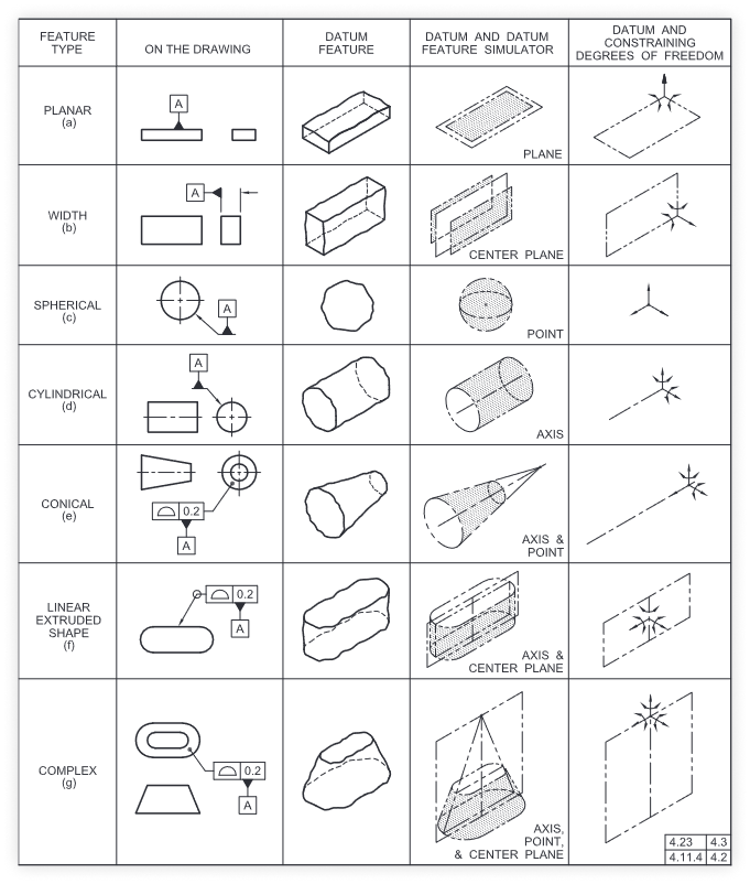
There are many ways to define a datum reference frame, but they all involve selecting datum features. The exact datum features that you select will dictate the manner in which constraints are applied to a part. Remember that the chosen datum features must fully constrain the part in order for a proper DRF to be defined. This reference table lays out the various datum features and how they constrain degrees of freedom along with how the datum feature callouts appear on a drawing.
Theory into practice: two example parts for building DRFs
In this section we’ll use a two example parts to drive home the key concepts we’ve already discussed. Each example will show the 3D geometry along with the proper datum feature callouts on the drawing. These examples will be in increasing order of complexity and will include a discussion of part and assembly design intent and how it relates to the chosen DRF.
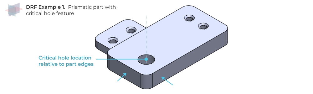
Prismatic part with critical hole location
Suppose you have a prismatic part with a critical hole feature that must be located accurately with respect to the part edges.
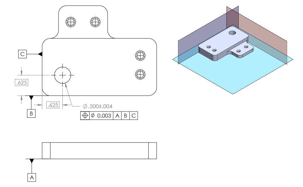
In this case, we can directly choose the part faces as datum features. Here’s what the resulting drawing looks like along with the DRF visualized relative to the part.
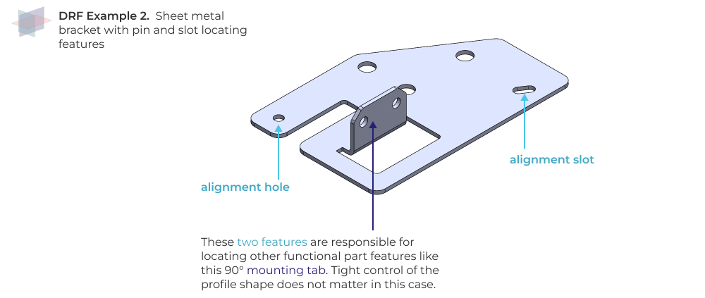
Sheet metal bracket with pin and slot locating features
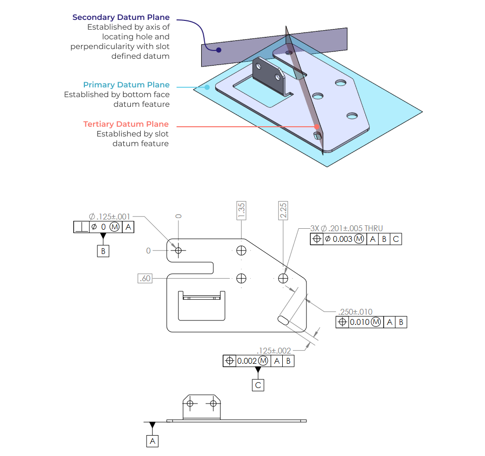
Now lets suppose we have a part that functions as an alignment bracket. It is meant to be located via pin and slot features. There are numerous critical features (e.g. hole groups) that must be located accurately relative to the pin and slot alignment. The profile of the part does not need to be tightly controlled because it does not directly impact design functionality. In this case we can build a datum structure that leverages the hole and slot features themselves.
Building our DRF
The primary datum will be the bottom face of this part, because we want a great reference for component flatness and perpendicularity of critical features, and because it’s just a practical approach that recognizes how the part will be measured on a surface plate. The secondary datum will be the precision hole, locating the part in the x-y plane (translation only). Finally, the tertiary datum can be defined by the slot feature. This places a datum plane at the mid plane of the slot, which ‘clocks’ the part and prevents rotation about the z axis.
Here’s what the DRF looks like on the part and what the datum feature callouts look like on a drawing.
GD&T is complicated → You need a review process
Despite the best intentions of engineers that use GD&T, it is sometimes confusing. In most cases, it helps to run a simple drawing review process or peer check for anything with a modicum of geometric and dimensional complexity. If you want to put in place a review process that eliminates mistakes, shortens development cycles, and guarantees you’ll design and build better hardware, check out our Ultimate Guide to Drawing Reviews. You’ll learn how to institute a frictionless drawing review process no matter what stage of product development you are working through.
Five Flute - Next generation collaboration for hardware product development
If you are a design engineer or technical project manager and you want to design better products in less time, consider Five Flute. It’s the fastest way to share, review, and improve your engineering designs. From engineering drawing reviews to 3D design reviews of complex parts and assemblies, Five Flute is built for modern engineering teams that want to move faster without making mistakes.
You might also be interested in
Five Flute drawing review checklist
Drawings 101 - The basics of creating high quality engineering drawings
Mastering GD&T: Material modifiers on data reference frames (coming soon)