CNC machining is perhaps the most important manufacturing process to understand as an engineer. Not only for individual part design, but also because CNC machining is used to create the majority of the tooling used in other manufacturing processes like injection molding, stamping, forging, some casting processes and extrusion. At Five Flute, we think of CNC machining as the “mother process” because it enables the manufacturing economy. Because of this, it’s incredibly important to have a solid base of CNC machining design for manufacturability (DFM) knowledge as an engineer.
In this article, we’ll be taking a deep dive into CNC machining DFM. We’ll start by building an understanding of how modern CNC milling machines work and what capabilities are typical. Then we’ll dive into the machining process itself by focusing on tools, setups and machining strategies. With this knowledge in hand, we’ll lay out what drives cost in CNC machined parts and how we can control cost in design. Finally we’ll close with an examination of DFM guidelines at the feature specific level before bringing all the concepts together with some example parts. By the end of the article you should be armed with a fundamental knowledge of DFM for CNC machining, not just a set of boilerplate design rules.
CNC milling machine overview
Most job shops today have a mix of 3 and 5 axis cnc milling machines. These machines typically have the ability to load and hold 20 - 50 tools, automatic tool changing capability, both air and fluid cooling systems to keep cut temperatures down and control chip flow, 1000 inch per minute rapid speeds in X and Y motion, and spindle speeds between 8,000 and 15,000 RPM. This makes them suitable for cutting a wide variety of materials, from soft engineering plastics like UMHWPE to harder steels, titanium, and aerospace alloys like inconel. In addition, many shops will have machines with automatic tool setting systems that allow them to accurately measure tool length and diameter, and then compensate for any geometric differences from the ideal tool geometry on the fly. Touch probes like the Renishaw OMP60 are used to measure part and workholding positions to setup jobs, as well as for in process inspection and quality measurement.
Machine architecture overview
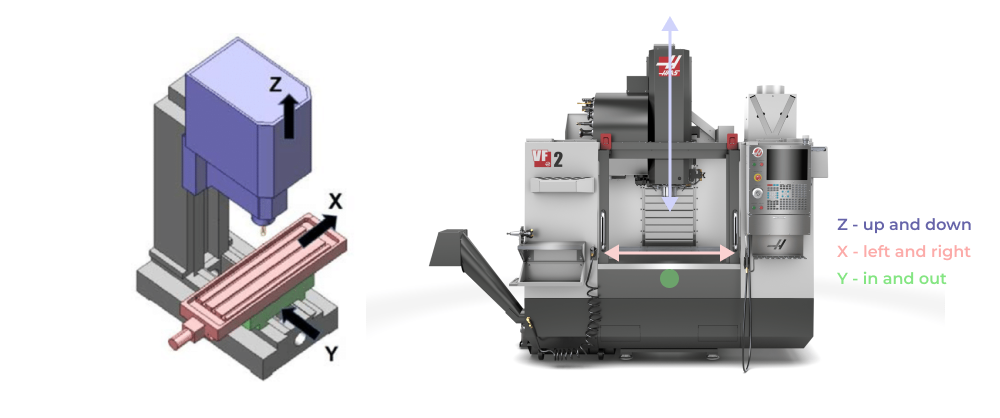
3 axis vertical mills
A 3 axis milling machine like the Haas VF-2 has a simple architecture with a base and column casting. Vertical milling machines have rectangular milling tables that move in both X and Y axis, typically affording almost twice the table travel in the X axis compared with Y axis travel (for example: approximately 40in x 20in travel for the VF-2). Z axis motion is achieved by moving a cantilevered spindle up and down the column.
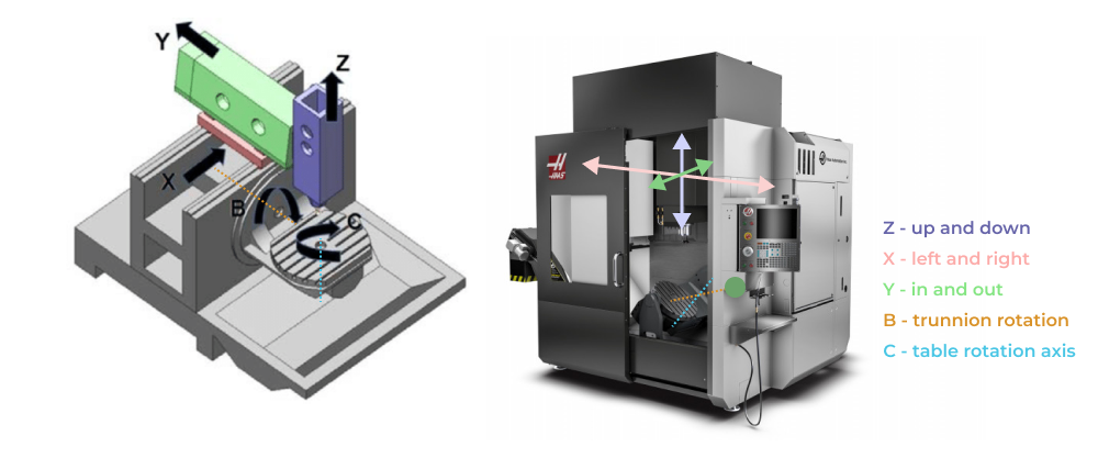
5 axis mills
5 axis mills come in a more diverse set of configurations, but generally include the additon of two rotational degrees of freedom (often called a B and C axis) on top of X,Y, and Z linear axis motion. Some mills are design more for indexing components with the B and C axes (used for 3+2 machining strategies), while others are designed for full simulaltaneous 5 axis motion (used for more complex geometry like turbine blades, blisks, and complex surfacing).
Understanding the machining process
In order to understand the relationship between the parts and features we design, and their associated cost and manufacturing complexity, it helps to have a complete understanding of the machining process.
Typical steps in CNC machining process
CNC machining starts with planning out the job and programming machines, this is non-recurring engineering work (NRE) that happens once per job. Then stock material is selected and cut while the machines used for part production are setup. This setup includes loading and setting tools, installing fixtures and workholding elements, as well as measuring and setting work offsets for each program. After this work is done, all that remains is to cut any custom fixture components (such as softjaws) and then run each operation of the job. After the part is produced, there may be some measurement and quality inspection before final packaging and shipping to the customer.

Common jobshop tools
From a DFM perspective its crucial to know what tooling is standard and available at most shops, so that you can design features that can be easily cut with these tools. The most common milling tools are summarized in the graphic below. Check out this article in our resources guide for more info on common milling tools that most job shops have.
Common workholding setups and machining strategies
3 Axis milling of prismatic parts
The most common setup in any shop is a basic machine vise with a work stop. This is used for holding square edged materials like stock bars and prismatic parts.
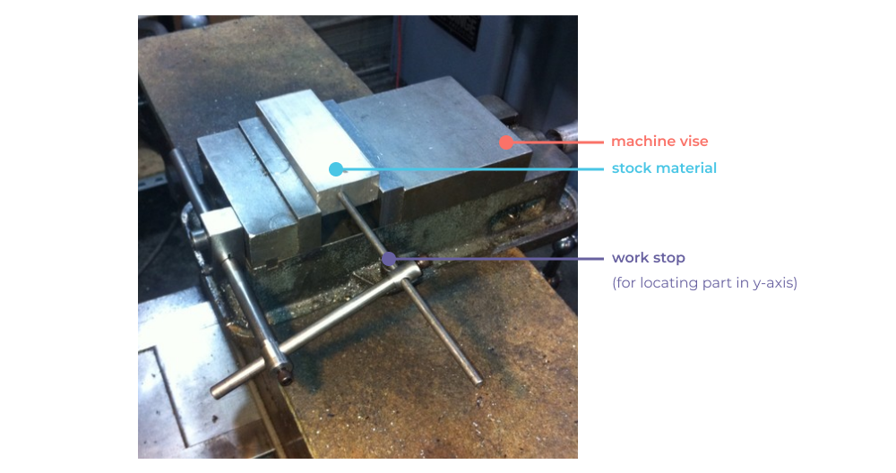
The vise locates the part in x and the workstop sets the position in y. Parallels can be used in the vise jaw to control the height of the clamped workpiece.
3 Axis milling with softjaw fixtures
The most common custom fixture in any shop is a softjaw. Softjaws are custom machined vise jaw profiles made to match the profile of the in-process part they are holding. Softjaws are often used on one vise in a double vise setup where the first operation of the part is cut on the first vise, then flipped into a set of softjaws for cutting the second operation, thereby making a complete part in 2 operations.
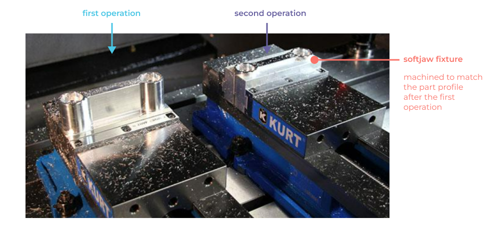
The key DFM concept with this setup is that all the features of the part must be accessible from two opposing faces. Design using standard tools and with antipodal feature access is a great recipe for keeping part cost down and quality high.
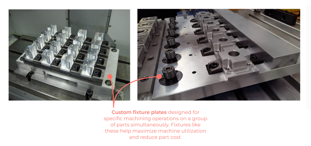
3 Axis milling with custom fixture plates
When cutting parts in larger quantities, it becomes important to maximize machine utilization by cutting multiple parts concurrently. Custom fixture plates (using workholding devices like the Mitee Bite Pitbull Clamp) allow compact and secure fixturing of stock material most often used for cutting the first operation of a part. These setups are often combined with multi vise softjaw setups for second operations in a different machine.
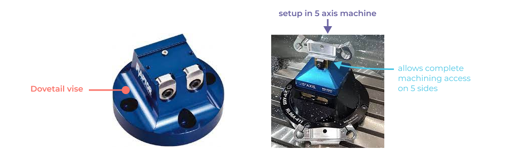
5 Axis milling with dovetail vises
The dovetail vise setup is employed on 5 axis machines so that 5 sides of the part can be machined in a single setup. Although they require additional preparation time to cut a dovetail feature into the stock material, they save time and money by ensuring efficient utilization of a shop’s more expensive 5 axis CNC machines.
Uncommon and custom tools
As a designer, it can be helpful to know if the features you design are manufacturable with more exotic, but still off the shelf, tools, or if a custom tool may be manufactured specifically for the purpose of cutting special geometry. Sometimes geometric complexity is unavoidable, but a working knowledge of less common tooling can and should be part of your DFM toolkit. It can mean the difference between expensive multi axis machining setups and a simple 3 axis machining setup, saving time and money. In this section we’ll go over some of the less common CNC tools along with a brief look at custom tool geometry.
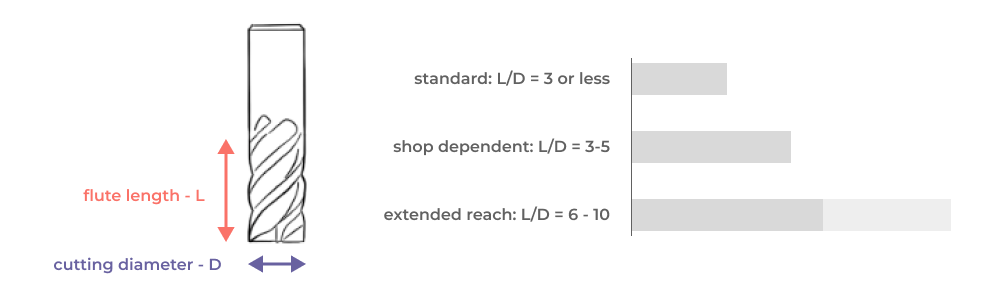
Extended reach endmills
Most articles on CNC machining DFM establish arbitrary guidelines for the depth of features relative to the diameter of the endmill that cuts the feature. These are useful, but there are many workarounds available to machinists in order to cut deep pockets with tight internal radii. Extended reach endmills have extra long flute length relative to the tool diameter, enabling deep profile cuts at relatively small internal radii. Here’s a quick chart showing roughly what to expect in terms of tool (cutting) length to diameter ratios.
Relieved shank endmills
Relieved shank endmills take another approach to allowing deep pocket milling with small internal radii. Instead of increasing the flute length, the tool shank (area without cutting flutes) is ground to a diameter that is less than the diameter of the cutting area. This allows deep pocket cutting access without interference between the pocket sidewall and the shank of the tool

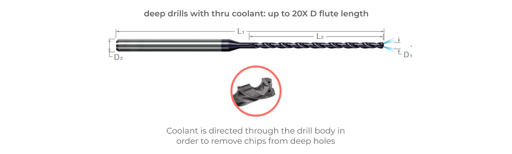
Deep drills
Deep bits designed for extremely deep holes include coolant passageways through the cutting flutes in order to remove cut metal chips from the hole. With these tools hole depths up to 20X diameter can be achieved.
Tapered endmills
Tapered endmills allow pockets to be machined with draft angle (tapered sidewalls) and are particularly good at deep cavity milling and surfacing in hard to access areas. They can also be combined with 5 axis simultaneous machining to cut extremely deep pockets. One advantage of tapered endmills is that they retain a high degree of lateral stiffness relative to their overall reach, allowing larger material removal rates for certain features and faster machining overall, at the cost of some programming complexity.

Lollipop cutters (spherical endmills)
Lollipop cutters allow up to 300º access to a spherical cutting volume. This can be used for complex three dimensional deburring operations and for cutting undercut chamfers and undercut surfaces in 3 axis setups.

Dovetail and dove-tail o-ring cutters
Dovetail cutters allow undercut dovetail profiles and slot features to be added in simple 3 axis machining setups. Most shops will have a standard 60º dovetail cutter that is used for preparing 5 axis material stock. If you need other dovetail angles, be sure to check availability with specific manufacturers. Note, some manufacturers make dovetail slot cutters specifically for o-ring grooves, so it’s best to design your o-ring grooves to match the exact tool geometry of the cutter. These tools are not likely to be in your local shop’s tool library, so it’s best to coordinate with them directly or put the part number of the desired endmill directly on your engineering drawing in a detail view of the feature.

Custom tool geometry
Companies like AB Tools can grind custom endmills to match your desired geometry. Generally this is used when production volume is high enough to justify the time and effort of making a custom tool, and when the custom tool can significantly simplify machining operations (making a 5 axis part suitable for 3-axis milling for example).
What drives cost in CNC machined parts?
Understanding the drivers of manufacturing effort, and associated part cost is a critical aspect of DFM for CNC machining. In this section we’ll unpack the cost function of a CNC machined part, breaking down each parameter and grouping them based on how their impact on cost scales with manufacturing volume. This will give you a better understanding of how DFM guidelines and feature specific recommendations can be applied as you transition from prototype to production.
Fixed cost factors
The following steps in the process are amortized across the total number of parts produced.
Programming and Non Recurring Engineering (NRE)
Planning the machining job and programming the toolpaths is a significant one time cost for each job. For prototype runs of complex parts, this can represent a significant portion of total job cost. From a DFM for CNC machining perspective, there is a direct relationship between feature complexity and programming complexity. Always design for the simplest possible machining strategy and workholding setup with commonly available tools.
Job setup (at the machine)
Job setup is also a fixed cost that is amortized across the total quantity of produced parts. DFM guidance for job setup is similar to reducing programming cost. Ensuring that your designs can be manufactured with boilerplate setups (doube vise + softjaw) is a great way to reduce job setup cost in both prototype and production.
Factors that scale linearly with production volume
The following factors drive the cost of CNC machined parts in direct proportion to the number of parts produced.
Material and certifications
Each part produced needs to be machined from a piece of stock material. From a DFM for CNC machining perspective, you should consider how much stock material is required to make the part only when production volumes get very high (10,000+ parts). Generally stock material is recycled efficiently in CNC machining so optimizing material usage is not a big driver of DFM cost reduction in CNC machining.
Part setup
Each part produced needs to be setup in a fixture, and this work is almost always done manually. Though some CNC machines are tended robotically, the vast majority of part setup time is operator manual labor during which the machine is not running. Simple fixtures are easier to load reliably, so focus on simplifying setups for your designs. Note that part setup time can increase with high tolerance requirements because it places a higher burden on operators to clear chips and clean any debris off fixtures and work stops.
Tooling
Regardless of the material being cut, tooling eventually wears out. This tooling wear is priced into your parts. The more parts cut, the more tooling wears out. From a CNC DFM perspective, the best approach here is to minimize the amount of material removal required to make your parts. At the extremes, this can mean designing a part around a specific available stock size, such as standard extruded bar profiles for example. Tooling wear is generally not worth worrying about at prototype quantities, but can become critical in volume production (on an iphone body for example).
Machining time
Machining time is a direct function of the part geometry. As a designer interested in reducing part cost while maintaining or increasing part quality, it’s very helpful to know how the features you design will impact machining time. Fundamentally want to understand how the features of your parts impact material removal rate. Material removal rate (MRR) is driven by the capability of tooling, with larger and stiffer tools like facemills capable of removing large amounts of material, and smaller, feature specific tools like a 1/8” ball endmill cutting very slow feedrates with minimal engagement. Keep in mind that this has a nonlinear effect as tooling gets smaller. MRR can also be limited by workholding. A very soft and compliant part cannot always be held firmly in a vise, so feeds and speed are often reduced in order to reduce the amount of cutting force applied to the part.
We will cover elements that drive machining time in the feature specific guidelines section of this article but some basic principles are worth mentioning here.
- Design all features to be cut by the largest tools possible.
- Try to enable the bulk of the material removal to occur during the first operation, when the workholding is most secure and the part in progress is still stiff.
- Surface finish requirements slow down cut speeds and have a non-linear impact on machining time.
- Smaller parts = less machining.
- Designs with a large ratio of part volume to stock volume = less machining.
- Larger tolerances = faster machining.
- More secure workholding = faster machining.
- Stiffer parts = faster machining.
- Softer materials = faster machining.
- Non-standard chamfer angles, external fillets, and complex surfaces may require surface interpolation with a ball or bullnose endmill at a very tiny stepover amount, meaning machine time to create these features can increase massively. They are not technically difficult to produce with modern CAM software, but they can be quite slow.
Tight tolerances
It seems intuitive that tighter tolerances will increase machine time, but the degree to which tolerance requirements can have a non-linear and dominant impact on machining time is worth examining. The chart below shows a normalized cost vs tolerance comparison across a range of tolerance ranges, note that the x-axis is log scale!
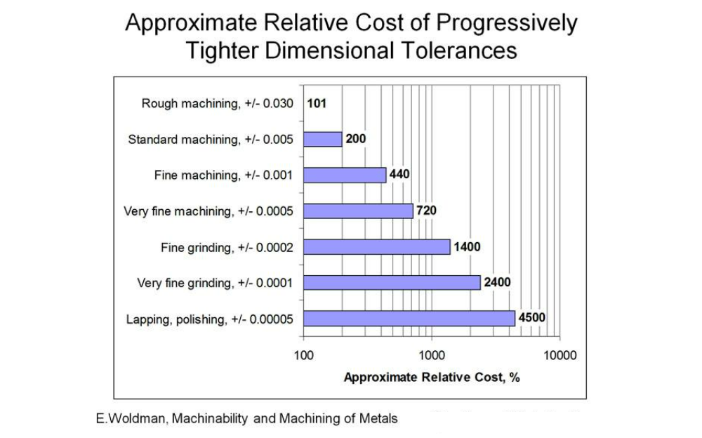
This nonlinearity in cost increase is driven by the need to control multiple process variables when tolerances tighten significantly. At a certain point, the accuracy and repeatability of the CNC machine itself must be considered, along with the deflection of tools and workholding, and even the temperature of the workpiece and the coolant! Very fine machining (on the order of ±0.0005”) brings these process control factors into play and some shops are just not equiped to deal with them well (no AC for example!). This is why your tolerances should never be an afterthought, and a thorough look at them should be part of your drawing review process.
Inspection
Inspection requirements are linked closely with tolerances. From a DFM cost reduction perspective, eliminating inspection requirements entirely, or limiting them to key functional interfaces can have large impact on inspection effort. Additionally the feature complexity can drive what kind of gage is required to measure the feature. A go/no-go gage on a hole is a cheaper quality check than a bore gage inspection that needs to be accurate to 0.0002”. Similarly, caliper measurements are orders of magnitude less costly than CMM inspection and associated reporting. Bad GD&T can often be a driver of inspection cost by poorly relating the functional interfaces of the part with the datum structure and by causing expensive datum feature simulators to be created unneccessarily. For more on datum structures and datum reference frames, check out this article in our guide.
Feature specific guidelines and design principles
In this section we’ll be outlining guidance at a feature by feature level. Keep in mind that DFM guidelines exist on a continuum. Every part has unique requirements and every manufacturer has a unique set of manufacturing capabilities. Because of this, we generally shy away from one size fits all rules of thumb, and instead choose to outline the DFM principles at play for each feature. The goal of understanding a feature specific set of CNC machining DFM guidelines is to simplify manufacturing while meeting function requirements, thus decreasing part cost while increasing quality and consistency of the parts and products we design.
Part profiles
The outer profile of a part consists of the faces which are parallel to the z-axis of the machine.
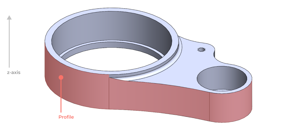
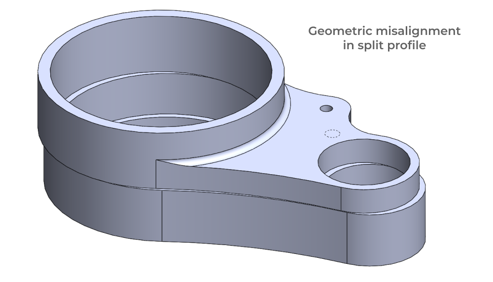
The depth of this profile is constrained by the flute length of the largest possible tool that can cut the profile. Maximum tool size is driven by the smallest internal radius on the profile. For parts with deep profiles, the profile of the part can be cut in two separate operations from opposing ends of the part. This requires the workholding accuracy between operations to be sufficient to blend the profiles from two different operations.
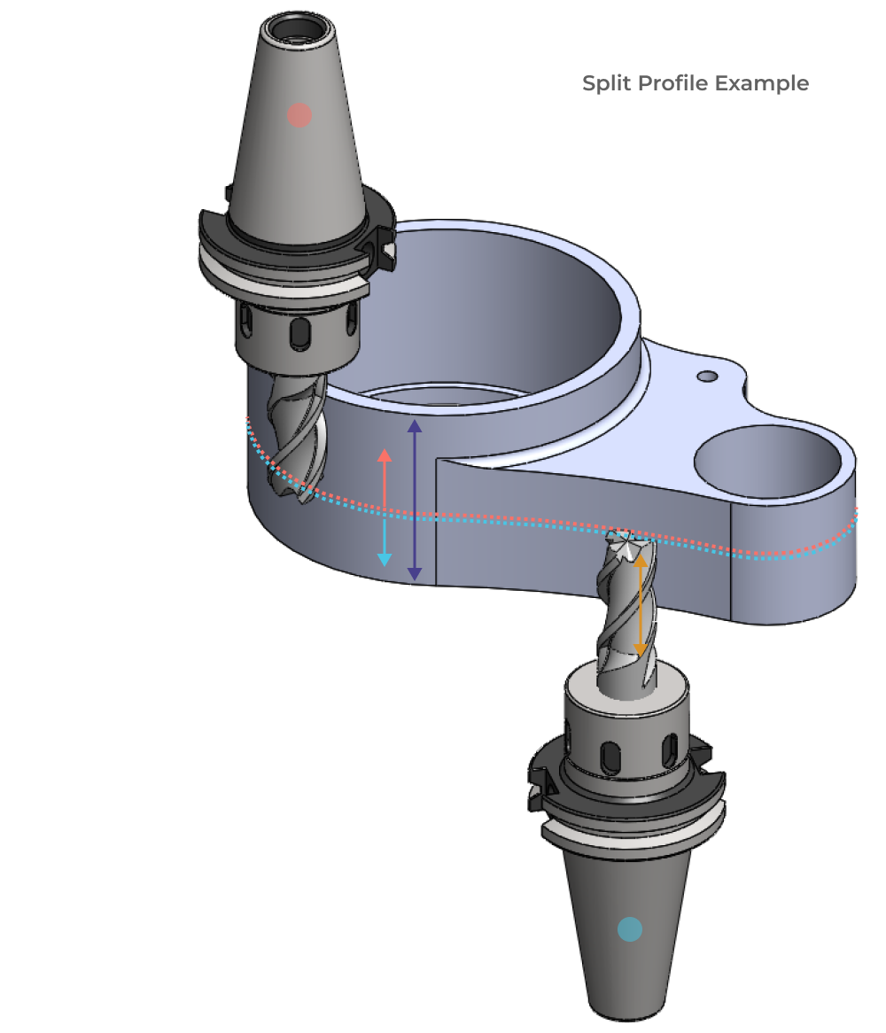
Misalignment during fixturing can result in a discontinuity at the surface which is shown as exaggerated geometry below.
Pockets and flat bottom holes
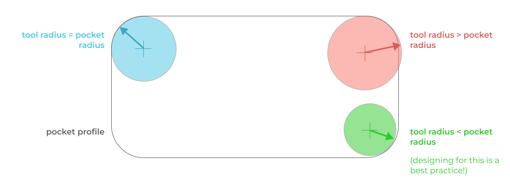
Similar to part profiles, the depth of pockets and flat bottom holes is constrained by the flute length of the largest possible tool that can cut the pocket. Maximum tool size is driven by the smallest internal radius on the pocket. It’s a best practice to design for the pocket to be cut with a tool that has a smaller radius than the smallest pocket radius. This allows for more even cutter engagement throughout the pocket contour and better surface finish.
In general you want to aim for pocket depths to be 6 tool diameters deep at a maximum. Above this depth, most shops will need to buy special tooling. This is not necessarily a problem, but it will impact schedule and cost. Pockets with a depth of 10 x D start to become challenging regardless of what tooling is available. Obviously this guidance is all material, tooling, and geometry dependent, but you should be aware of these threshholds of manufacturing difficulty as an engineer. The more you push the limits, the more you will need to work with your suppliers to confirm manufacturability.
Fillets and chamfers
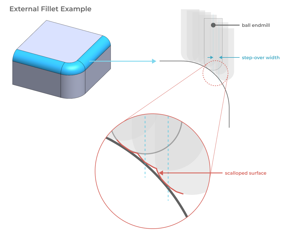
Fillets with a primary axis that is not parallel to the spindle of the milling machine will generally be cut by surfacing toolpaths. Surfacing requires a ball endmill 3d contouring operation with a small stepover. This is faily simple to program with modern toolpath generation software, but it will result in small scalloped geometry driven by the stepover width of the toolpath. When designing these features you should know that they will take more machine time and will have a visibly different surface finish.
The same guidance goes for chamfers of non-standard angle. Chamfer tools are commonly available in 60º, 82º, and 90º included angles. If you really need a chamfer angle of 32.5 degrees, it will be a surfaced feature.
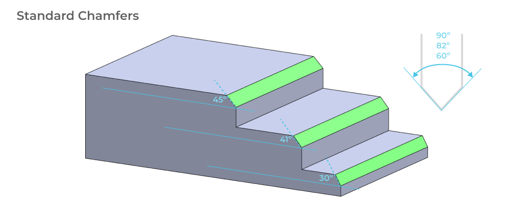
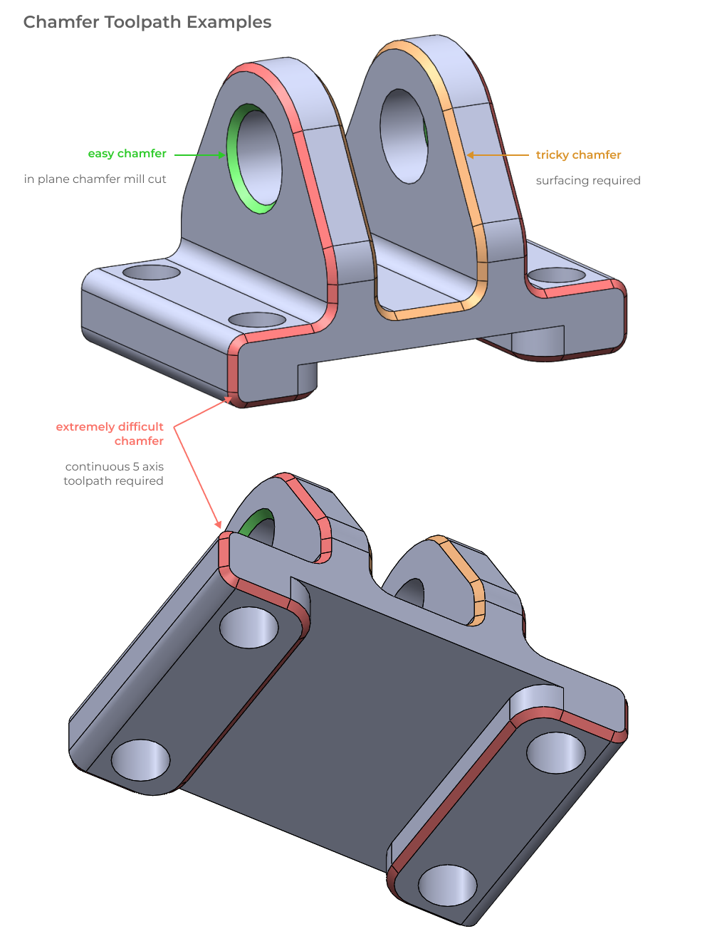
Since chamfers are a very easy feature to add in CAD, designers can often add them in for aesthetic reasons, without much deep thought given to the machining implications. In the case of parts with chamfers that are continuous across multiple different planes, either surfacing or continuous five axis toolpaths are required. This is a significantly more challenging machining operation that limits the number of machines that can cut your part, likely increasing both lead time and cost. While it is possible to cut these geometries, the effort is significant, so be sure to understand if they are necessary. The example below shows three chamfer features of increasing difficulty. The first (marked in green) can be cut by a simple 2d milling operation with a chamfer mill. The second (marked in orange) can either be surfaced with ball endmills or cut with a continuous five axis operation. The third, and most difficult chamfer (marked in red) would either require surfacing operations in multiple setups or a continuous five axis operation and some clever fixturing (because of the undercut and multi-plane nature of the chamfer path).
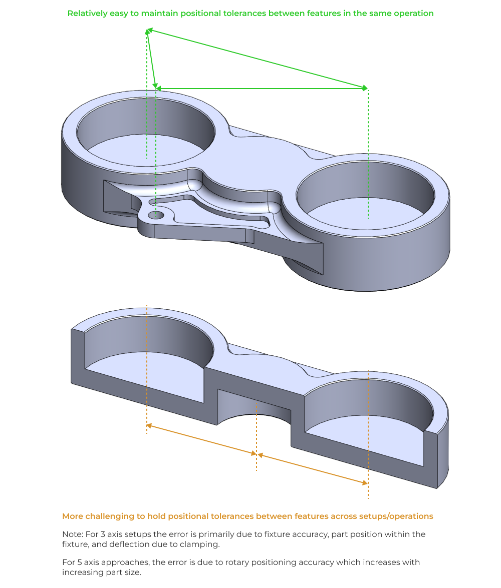
Tolerances across setups
When possible, features with tight relative tolerances should be designed to be machined in the same setup. Because of the high positional accuracy (approximately ±10 microns) of CNC machines, tight tolerances are easily achievable when features are cut in the same setup. This approach removes the positional uncertainty introduced by refixturing in vises and softjaws for secondary operations. From a practical perspective, designers should focus on making critical features coplanar and simple to access with standard tools.
Vibration and thin features
The cutting forces induced in machining operations are impulses with a broad range of frequency content. This naturally excites a variety of vibration modes in the workpiece. As features and wall thicknesses decrease in size, vibration and damage induced by machining become an issue. Most of the guidance on this topic is limited to rigid rules around minimum thickness, but this neglects the reality that local thickness and stiffness do not necessarily correlate. Here are some common features to be on the lookout for.
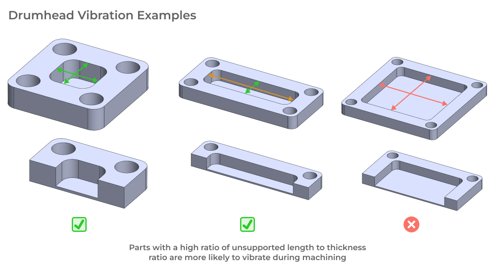
Thin pocket floors
Pocket features can sometimes leave a thin floor that behaves like a membrane or drumhead. The important factor from a design perspective is to look at the unsupported surface area in proportion to the membrane thickness. The larger the unsupported length of this surface area, the higher the risk of vibration during machining.
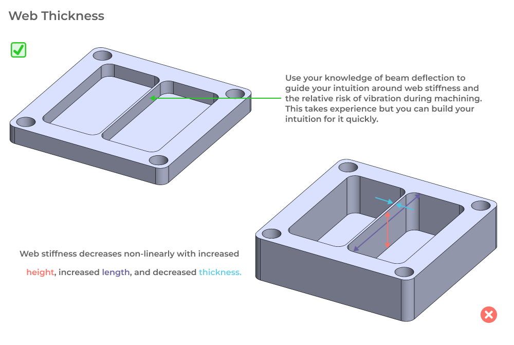
Thin webs without intermediate support
Similar to pocket floors, stiffening webs used in aerospace and other light weight parts can be susceptible to vibration during machining. The key is to build your intuition for the stiffness of these features by leveraging your understanding of beam deflection formulas. As the section modulus of the web cross section decreases, there is a non-linear decrease in stiffness, thereby increasing the vibration risk during machining.
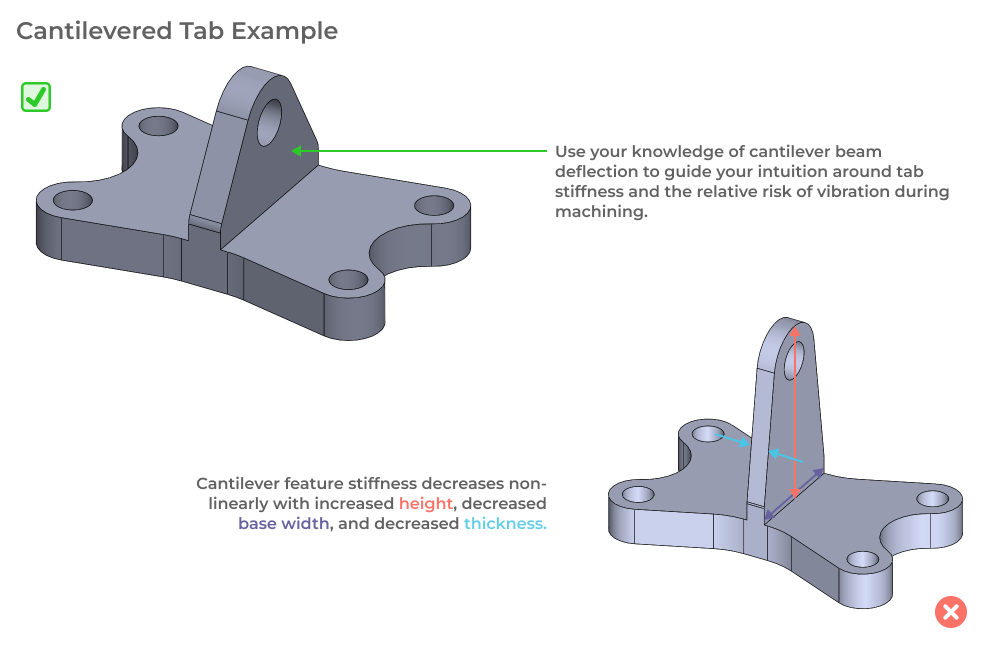
Cantilevered features
Cantilevered features (like tabs and snap fits) require similar intuition regarding stiffness as webs and membranes. Just keep in mind that a cantilevered beam is significantly less stiff than a simply supported beam, so be on the lookout for this kind of vibration during machining. Comparable guidance holds however, and you should try to strike an appropriate balance of tab height, base width and thickness that will ensure the feature can react cutting forces without significant deflection.
Undercuts
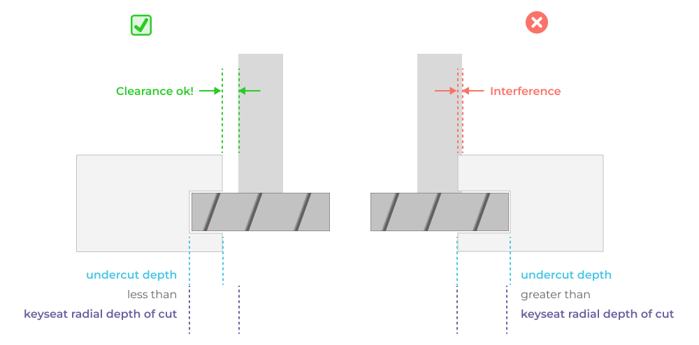
The key question to ask youself as a part designer when adding undercut features is, “Does this require an additional setup or 5 axis machine to access”? In order to answer this you need to know what kinds of undercut features can be cut with off the shelf keyseat cutters and slitting saws. Keyseat cutter geometry limits undercut feature depth because the arbor of the cutter may interfere with the sidewall of the part.
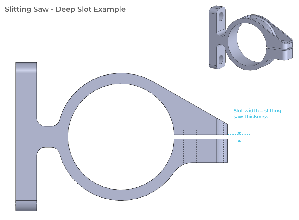
Slitting saws have a large cutter diameter relative to arbor diameter and can be used for cutting deep slots. Because of the flexibility of the saw blade, you typically don’t want to machine deep undercut slots in multiple passes because you want balanced and symmetrical engagement of the tool. Accordingly, it’s best to design deep slots with a width equal to the thickness of the slitting saw. Here’s an example part demonstrating this best practice.
Warping and internal stress management
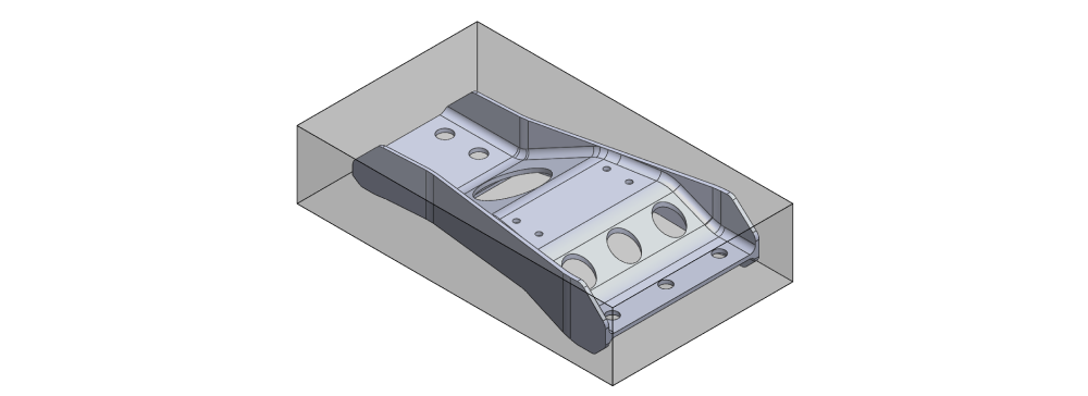
Stock material almost always arrives with an internal stress state that is non-uniform. Extruded aluminum bar for example usually has tensile stress at the surface and compressive stress in the core of the bar. When machining components from stock with internal stress, the machining operation can remove stressed material and cause warping.
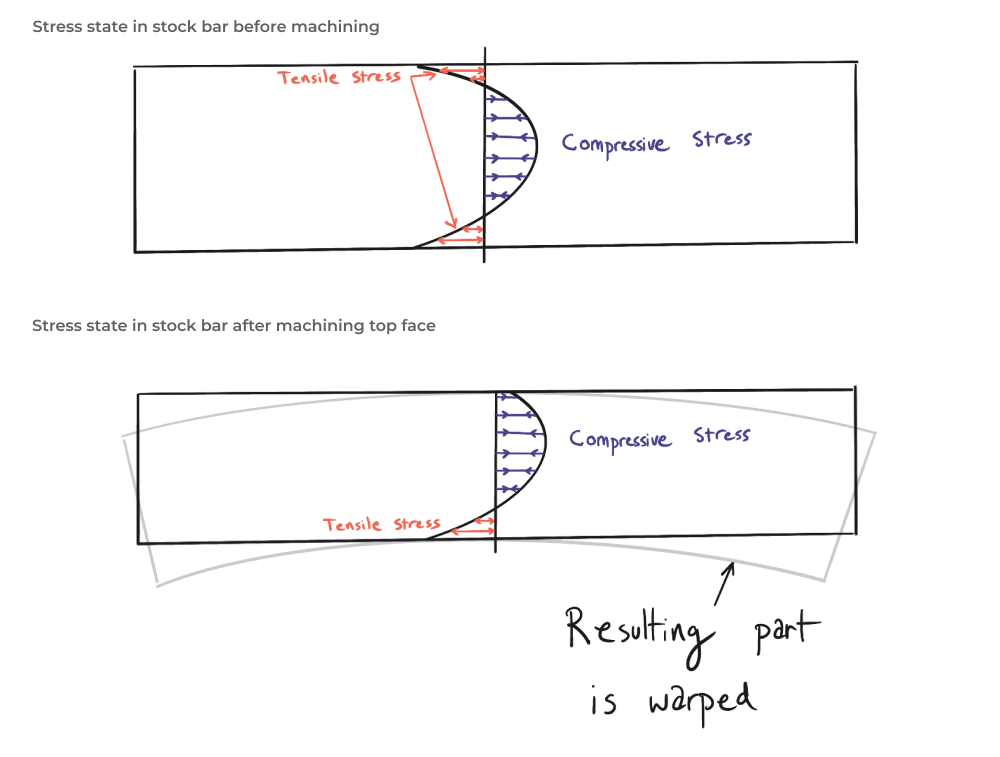
As a designer, you should understand that parts with asymmetric profiles and large amounts of material “hogged out” are more likely to exhibit warping when released from fixtures after machining. Machinists can manage this by balancing the location of the part within the stock material, but it is not always possible to avoid.
Design for workholding and (part compliance)
One of the most difficult aspects of DFM for CNC is understanding how your design choices impact workholding. Most parts are held in a straight vise jaw or set of custom softwjaws for machining the final operation. This means your parts will be clamped with significant force (hundreds of pounds) when they are partially complete. For certain designs the first machining operation will drastically reduce the stiffness of the part, making secondary operation workholding a real challenge. This challenge is twofold:
- Ensuring the part can be clamped hard enough to resist machining forces and stay held precisely in the vise.
- Ensuring the part does not deflect significantly as a result of workholding induced forces.
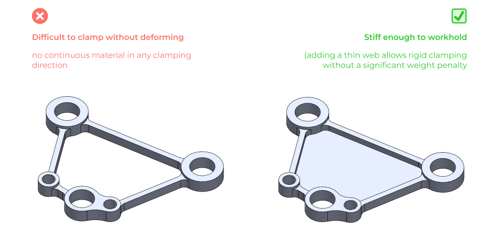
Note: machinists can compensate for compliant parts by slowing down toolpaths and increasing part cost. It is much harder to compensate for the impact of part compliance on tolerances. As a designer your general guidance should be to design geometry that can be clamped hard if you want it to be machined at low cost or with high accuracy.
DFM example parts
In this section we’ll be examining a few example parts and then looking at what modifications we can make from a DFM perspective to help reduce the complexity of manufacturing, decrease cost, and increase part quality. For each example we’ll show the initial geometry and then highlight design changes based on the high level principles and feature specific DFM rules we outlined earlier.
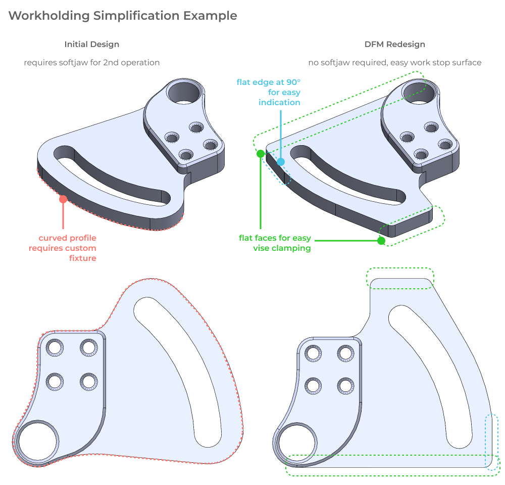
Design for simple workholding
In this example, let’s look at a relatively simple 3-axis machined part with the bulk of the features machined during the first operation.

Based on the geometry and our knowledge of common machining setups, it looks like this part would require a custom softjaw fixture to hold the workpiece during the second operation. How might we reduce the complexity of this setup even further? In this case, what if we made slight geometric modifications to allow the part to be fixtured in a standard (unmodified) machine vise. Additionally, we can add geometry to allow the part to be positioned repeatedly against a vise work stop. Here’s a comparison of the original geometry and the redesigned geometry with DFM for CNC best practices considered.
Reduce machining time
In this example, we’ll be examining how minimum fillet size and relative feature positions impact tool choice. The example part has a number of tight internal fillets as well as standoff features that are located close to eachother.
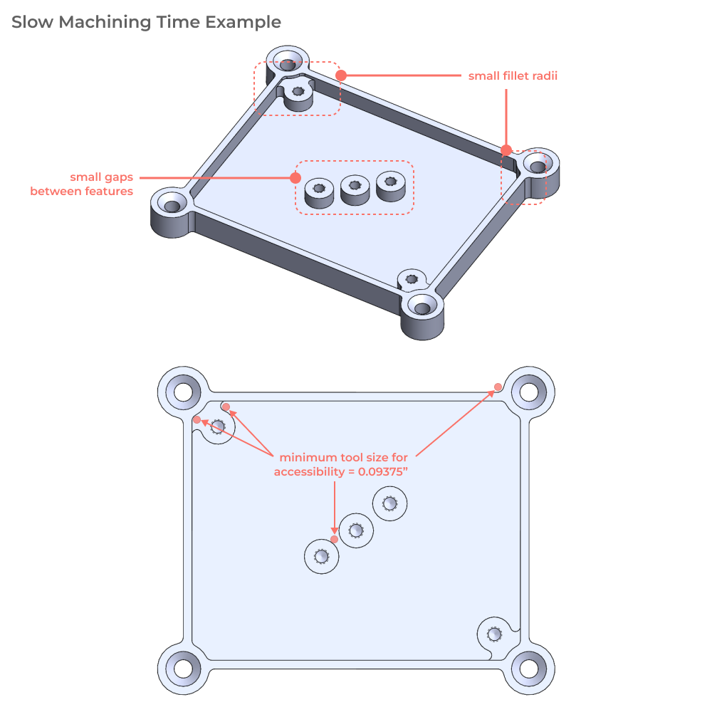
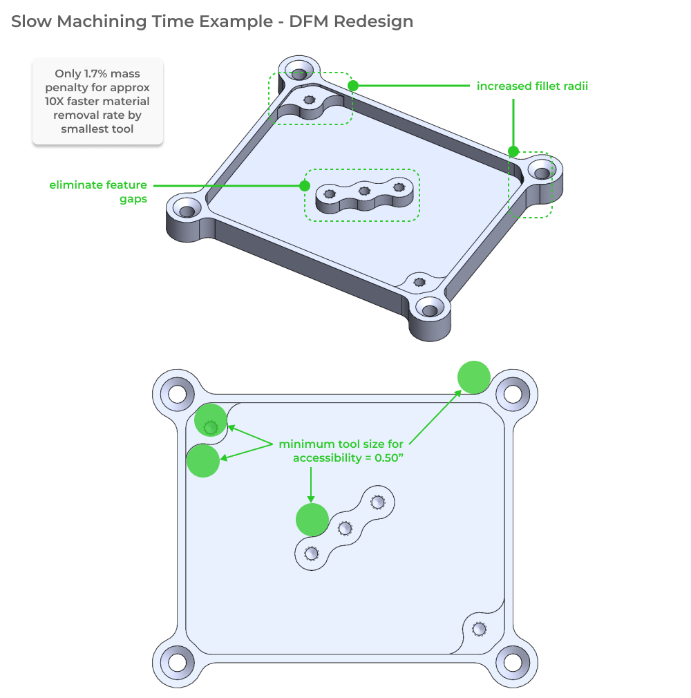
This part requires a 9/32” endmill to reach the small internal fillets, slowing down machine time and increasing cost. A relatively straightforward redesign exercise to increase fillet radii and eliminate small feature gaps can significantly reduce machining cost with a small but acceptable weight penalty.
Aerospace bracket - subtle simplifications
This example demonstrates how subtle changes in geometry can have a large impact on both machining strategy/setup and machining time (regardless of setup!). Below is our initial design for a 7075-t4 aluminum bracket designed to hold hydraulic components to an aircraft fuselage. The H-beam geometry is very structurally efficient for the load cases expected in service, but it may add difficulty during workholding in particular. Consider also that the lightening holes in the H-beam flange are machined normal to each surface, instead of coaxially.
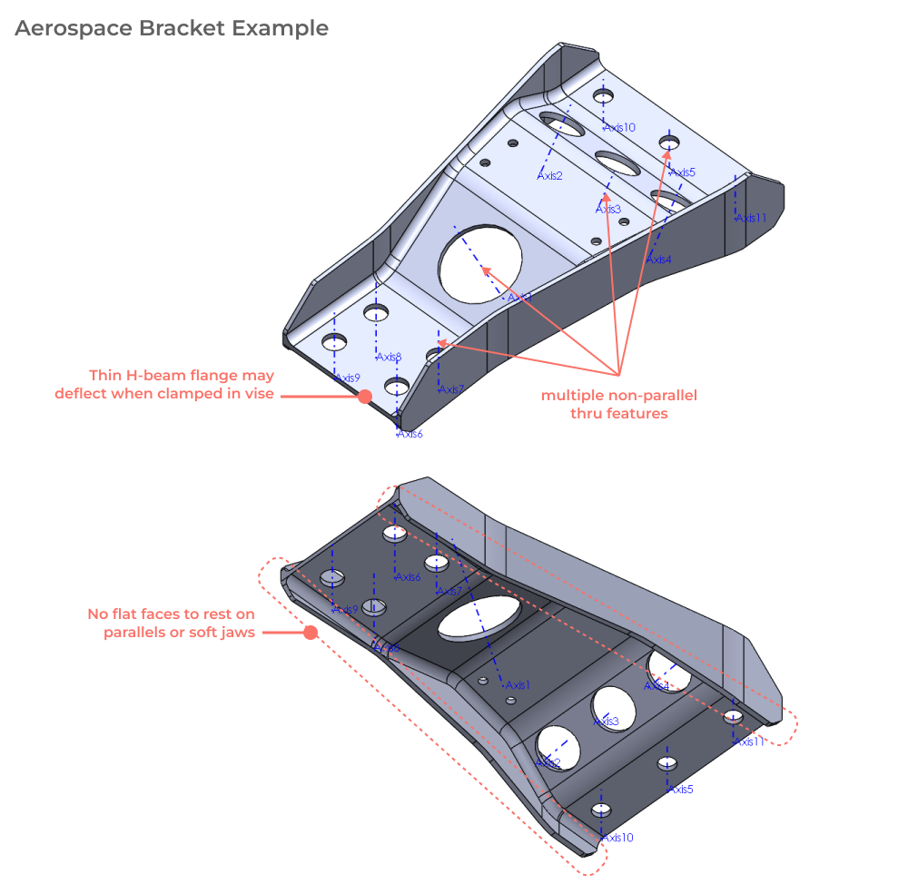
As currently designed this part has a number of issues:
- Requires multiple setups in 3-axis machine, or 5-axis machine in order to cut through-feature geometry
- May be difficult or impossible to machine quickly due to vibration of thin flanges.
- Will likely require a custom fixure for the final operation in order to support such a compliant part while also indicating it in repeatably in machine coordinate space.
With these issues in mind, lets take a look at a handfull of simple design for manufacturability changes that we can make to help reduce part cost and increase quality.
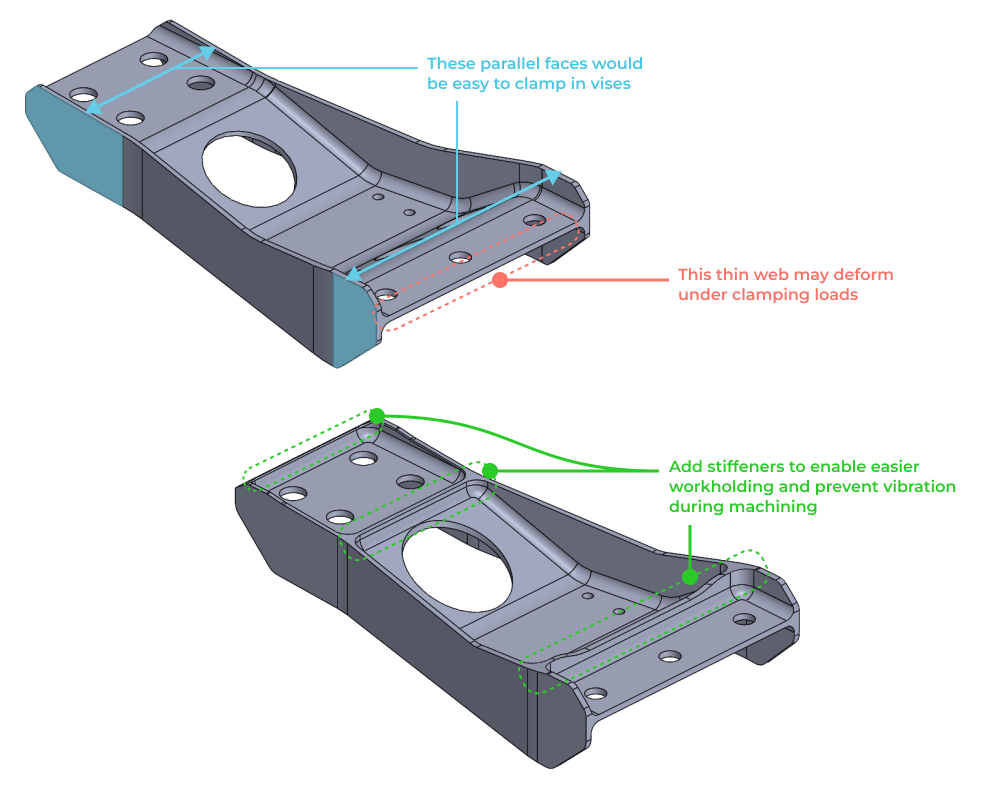
Increase stiffness to reduce vibration risk and compliance under vise clamping load
This geometry already has a few parallel surfaces that would be easy to clamp in a machine vise for the final operation. Without support between these flanges, the central web of the part may either vibrate during machining or bow out due to vise clamping loads. Adding stiffening ribs across the part can help mitigate this vibration and allow for easier and more secure workholding in a double vise setup.
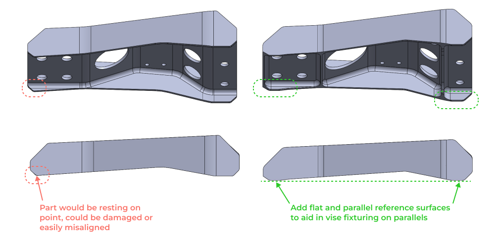
Add parallel reference surfaces to enable double vise workholding for final operation
This change is simple but impactful. When parts don’t have flat surfaces to rest on, repeatably locating them in the machine coordinate space becomes more difficult. Additionally you risk damaging the areas where parts rest if there is not enough surface area contact. This simple DFM change illustrated below adds flat and parallel reference surfaces so that the part can be rested on parallels.
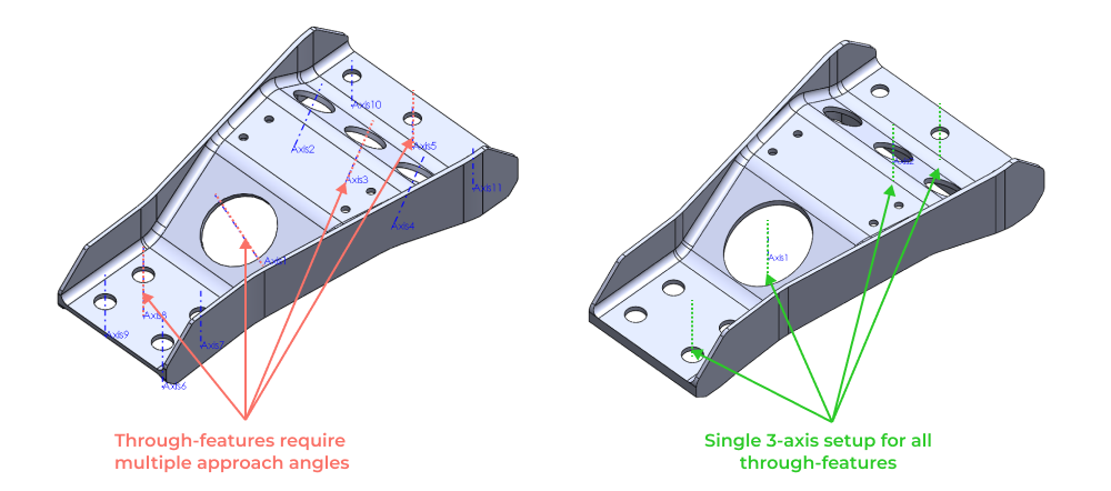
Simplify feature accesibility
Another simple change illustrated below is to ensure that all through feature geometry (both fastener holes and lightening hole geometry) is aligned such that it can be cut in a single 3-axis milling operation. Extrude direction in CAD is sometimes an afterthought, but it can have profound impacts on manufacturing complexity.
CNC component design reviews and drawing preparation
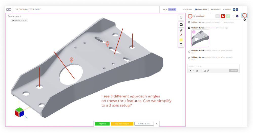
As with any design, mistakes are inevitable. At Five Flute we’re big fans of what we call a continuous design review process. Basically this means running lots of small design reviews so that issues are discovered early before designs develop inertia from integration, and are more costly to correct. Here’s a quick example markup showing how we used Five Flute's 3D design review capability in preparation for this article.
For your CNC DFM reviews make sure you check all of the features of your parts against the guidelines in this article. Also be sure to set up your review for success by preparing properly and executing a good review. We’re building Five Flute to help power your continuous design review process. Its the easiest way to share, review and improve your designs. To see it in action, sign up for a quick demo.
For your drawing preparation, check out our Drawings 101 article as well as best practices for drawing reviews, so you can catch any last minute mistakes before your parts are released. All of your CNC DFM work will be wasted if you can’t communicate the requirements of your parts to manufacturers efficiently.
Thanks for reading and good luck with your next hardware project!