As a design engineer you will likely use a range of materials in your part designs. More often than not, aluminum will be a go-to material for your machine design projects. Anodizing is one of, if not the most preferred finishing process for aluminum parts. It provides a corrosion resistant, durable, hard, and attractive finish on aluminum parts. In this guide, we’re going to dive deep into anodizing and anodized part design. We’ll cover the basics of the conversion coating process, the fundamental structure of coatings, how to specify them, and a range of design considerations that experienced part designers should know.
What is Anodizing and Why Use It?
Anodizing is an electrochemical process that converts the metal surface into a durable, corrosion-resistant, anodic oxide finish. This process is most commonly applied to aluminum, but other nonferrous metals such as magnesium and titanium can also be anodized. In aluminum, the outer surface of the anodized part is converted to a layer of aluminum oxide (hence anodizing is a “conversion coating”).
Anodizing can be used for a wide range of applications, but these applications typically leverage the following coating properties.
- corrosion resistance
- increased surface hardness
- decorative color/part dying
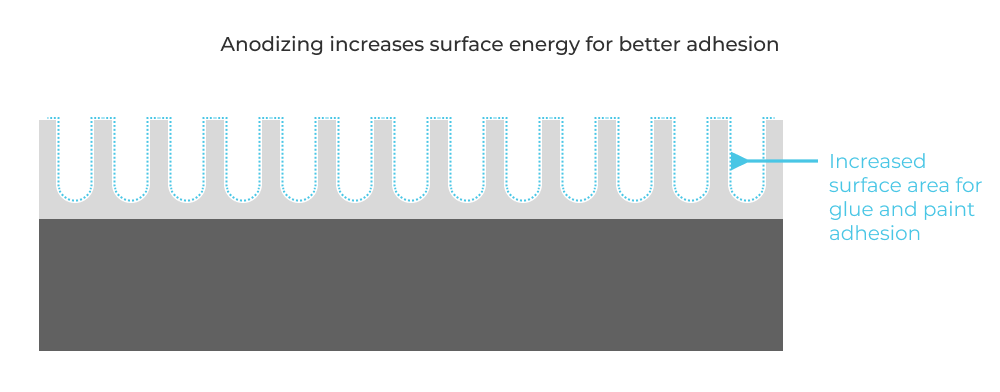
- modifying surface energy for better paint or adhesive adherence
- electrical insulation
- prevention of galling (with aluminum on aluminum component interfaces)
Typical Process Overview
Anodizing involves several key steps: cleaning, pre-treatment, anodizing, coloring (optional), and sealing. Let’s walk through each of these steps:
-
Cleaning. The workpiece is first cleaned to remove any contaminants. Usually an alkaline cleaner is used in order to remove grease and oils without actually damaging the underlying aluminum.
-
Pre-treatment. Pre-treatment may involve etching or brightening, depending on the desired finish. Etching is usually achieved though immersion in a sulfuric acid bath. In addition to further removal of contaminants, etching removes any non-uniform oxidization that may already be present on the part.
-
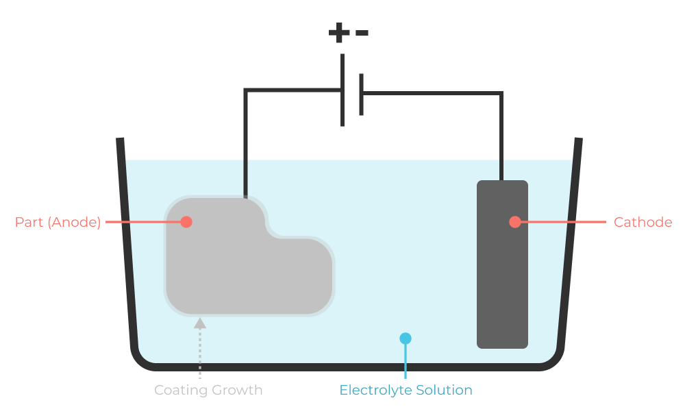
Anodizing. During anodizing, the workpiece is submerged in an acid electrolyte bath and an electrical current is passed through the medium, leading to the formation of the oxide layer. If you ever did an electrolysis experiment in high school, that’s all that’s happening with anodizing. The application of current causes water to split, thereby freeing up oxygen to migrate towards the anode. This converts the surface of the aluminum to aluminum oxide (AL2O3). Uniformity of current throughout the part (current density) enables careful control over the coating thickness.
-
Rule of 312: At a constant current density there is a simple rule (the rule of 312) to determine the coating thickness. Minutes to anodize = (microns (of coating desired) × 3.12) / amps/sq dm
-
Coloring. If color is desired, the porous oxide layer can be dyed just by dipping the part in a dye formula.

-
Sealing. Finally, the workpiece is sealed to close the pores, enhancing durability and increase corrosion resistance. Sealing methods range from hot deionized water, hot nickel acetate, mid-temperature, cold, and dichromate sealing, each with various impacts on coating quality and durability.
Passivation and Coating Structure
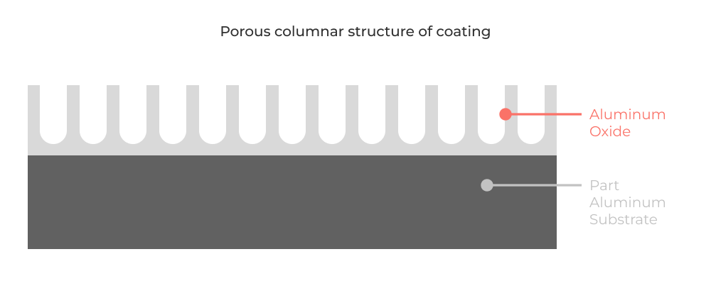
The anodizing process inherently includes passivation, where the outer metal surface is stabilized by converting it into a more inert form. This passivation layer is actually the anodic oxide itself, which is much thicker and more protective than the natural oxide layer that forms spontaneously on the metal. The anodic oxide structure originates from the aluminum substrate and is composed entirely of aluminum oxide. This is why it is called a conversion coating! The part is not being “dipped” in a coating like paint, but instead is undergoing a chemical reaction that fundamentally modifies the outer structure. The new coating structure is highly ordered, featuring porous columns that allow for secondary processes such as dyeing and sealing.
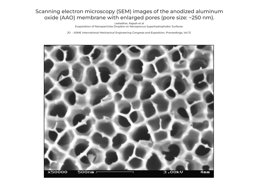
Looking at a section view, the coating is roughly columnar in structure.
Types of Anodizing and Relevant Standards
Anodizing is categorized into several types, with Types I, II, and III being the most prevalent. Each type adheres to specific standards and is suited for different applications.
Type I
Type I anodizing, also known as Chromic Acid Anodizing, is known for its thin coating and is typically used for parts requiring high corrosion resistance without the need for thick coatings. It’s often used in aerospace applications. The coating thickness ranges from 0.5 to 7.5 micrometers. Relevant standards include MIL-A-8625 Type I.
Type II
Type II anodizing, or Sulfuric Acid Anodizing, is the most common form, providing a good balance of durability and aesthetics. It’s suitable for a wide range of applications, offering thicknesses from 1.8 to 25.4 micrometers. This type allows for a variety of color finishes. Standards for Type II include MIL-A-8625 Type II and ASTM B580.
Type III
Type III, known as hard anodizing, produces the thickest coatings, offering superior wear and corrosion resistance. It’s ideal for components subjected to high wear or harsh environments. Coating thickness can exceed 25 micrometers. Standards include MIL-A-8625 Type III.
Coating Specification
When specifying an anodized finish, engineers should include the type of anodizing, coating thickness, color requirements, and sealing process. The specification may also dictate pre-treatment processes and any post-anodizing operations such as laser etching, gluing or printing.
Check out this incredible reference guide for more details on coating specification.
Design Considerations for Anodizing
As a design engineer, you don’t need to know every step of the anodizing process, but it is helpful to understand the relationship between specified coatings and the function of the finished part. Here are some considerations for you to keep in mind.
Coating Thickness and Part Size Growth
Anodizing increases the dimensions of a part. Engineers must account for this growth, especially for tight-tolerance components. The thickness of the coating should be evenly distributed, but this can vary based on the geometry of the part and the anodizing process used.
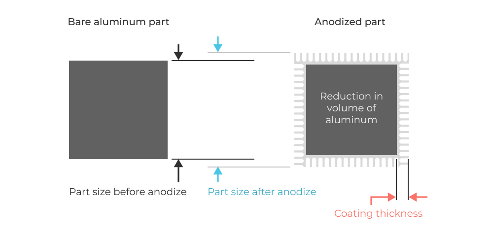
The rule of thumb that I’ve always operated by is that the part size growth is equal to 50% of coating thickness. For example, with Type III hard anodizing a 25 micron (0.001”) coating is created. This results in a uniform offset of 12.5 microns (0.0005”) from the part surface. Inner diameters therefore decrease by one coating thickness (2 x half thickness). This doesn’t sound like much, but for precision fits and tight tolerance parts, the part size growth absolutely must be accounted for.
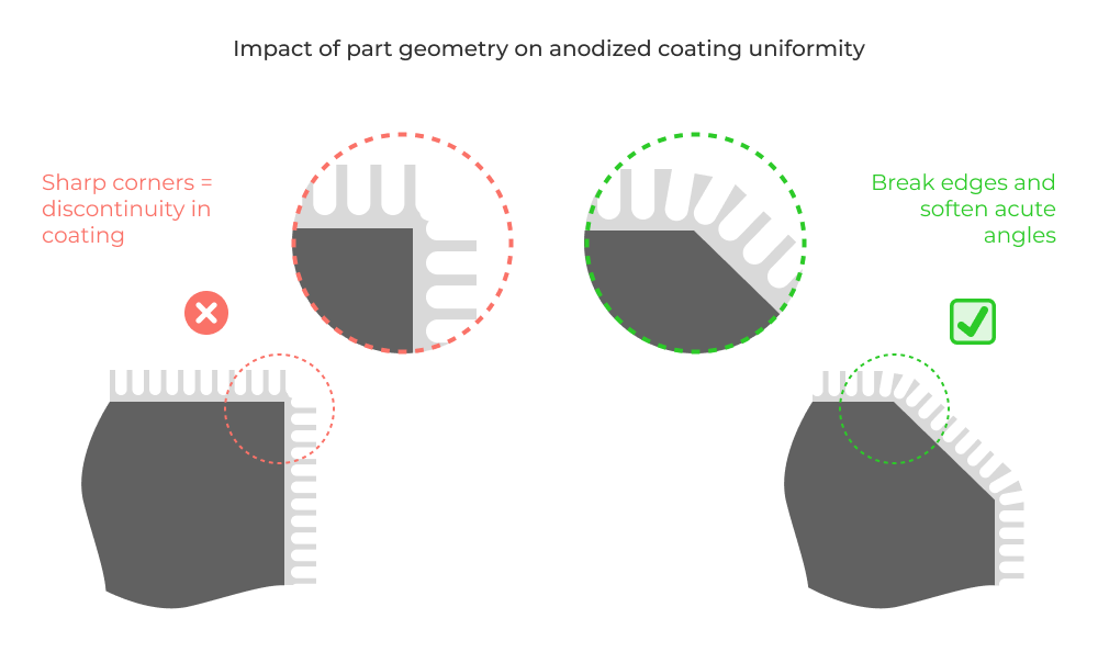
Pre-Conversion Geometry
The pre-anodizing geometry of a part can affect the uniformity of the coating. Complex shapes may require special fixtures or multiple anodizing steps to ensure even coverage. Keep in mind that the coating growth is normal to the part surface. This means coating thickness (and part performance) can be compromised by sharp corners.
Electrical contact (racking)
Electrical contact with the part is a prerequisite for the anodizing process. Importantly (and obviously) this means every single part in the coating bath needs to have a reliable electrical connection throughout the entire process. These areas of contact have no coating growth. This imposes an important design constraint on every anodized part. You need to pick this location carefully and specify it to manufacturers, otherwise they’ll pick it themselves. I highly recommend you visit a few anodizing shops so you can see the various part holding methods and how they impact coating distribution.

Masking
Because of coating thickness and part size growth, there may be areas of the part where you do not want any anodized coating. This can be achieved through the process of masking. Threaded and small diameter holes, bearing bores, and other tight tolerance features are often plugged or masked with electrically insulating material. This prevents current from passing through these features, inhibiting coating growth. In my experience, improper masking is the number one cause of anodizing rework.
For Type III hard coat anodizing I always mask all threaded holes. For Type II, I tend to mask threaded holes that are below 3/8-16 or M8-1, depending on the class of fit. Either way you should consider coating thickness and part size growth in your tolerance analysis.
Sealing
Sealing is critical for maximizing corrosion resistance and should be considered in the design phase, especially for outdoor or marine applications. It also helps to “lock in” the die inside the porous aluminum oxide surface.
Pro Tip: Are you working on components that need to have low friction? It’s possible to add a PTFE coating when sealing anodized parts. I’ve used this for light duty bushings and assemblies that have aluminum on aluminum contact. Ask your local vendors about this process.
Fatigue Life
Anodizing can affect the fatigue life of a component. The impact varies based on the type of anodizing and the base material, but generally, hard anodizing can reduce the fatigue life due to the stresses introduced by the thicker oxide layer. There are two mechanisms of action to consider:
- Crack formation and propagation. “As the coating thickness is equal to the initial crack length from a fracture mechanical point of view, stress intensities at the crack tips are higher for thicker coatings respectively longer initial crack lengths. Therefore, propagation of fatigue-induced cracks from the coating into the substrate is promoted for a higher coating thickness resulting in premature failure.” [Lisa Winter* and Thomas Lampke, Adv. Eng. Mater.2023,25, 2300394]
- Residual stress. “Fatigue-induced failure is further supported by the tensile residual stresses in the anodic coating, which result from the coating formation and the growth of the cellular-arranged pores. These tensile residual stresses are most pronounced at the pore base and at the interface to the aluminum substrate. The detrimental effect on the fatigue strength is enhanced by an increase in coating thickness as the number and size of irregularities in the anodic coating increase as well.”
Both of the above quotes are from this fantastic paper for the characterization of 6000 series aluminum subject to high cycle fatigue loading. Here’s my favorite takeaway quote from the paper:
“For the anodized aluminum alloy, the fatigue strength is decreased by 8% for 10 μm to 50% for 40 μm coating thickness. Therefore, the thickness of the anodic coating is a major influencing factor for the resulting fatigue limit and with an increase in coating thickness the fatigue strength is decreased.”
Paint and Adhesives
The anodized surface provides an excellent substrate for paint and adhesives due to its porous nature. From a first principles perspective, anodizing increases the surface energy of the substrate material. Keep in mind that the type of anodizing and the sealing process can affect adhesion properties as well. Check out this paper for more nerdy insights into the impact of anodizing on adhesion performance.
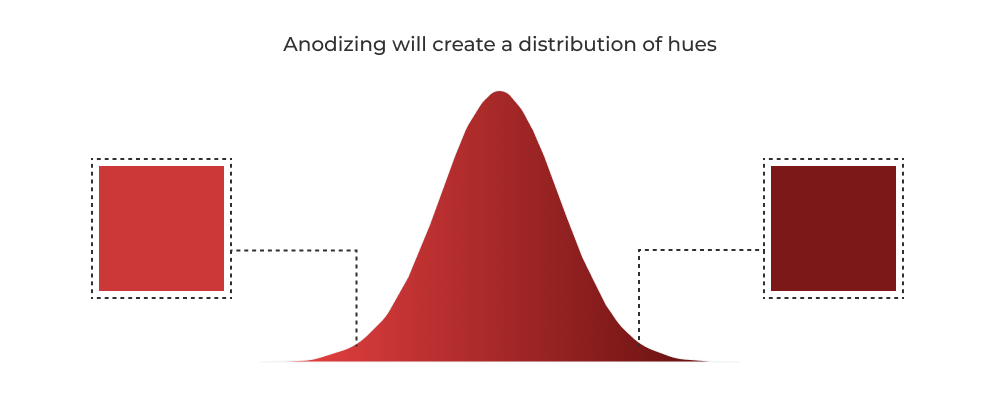
Color Matching
For applications requiring specific aesthetic considerations, color matching can be a challenge. Variables in the anodizing process can lead to slight variations in hue between batches. Consistent process control and testing are key to minimizing these differences. With that said, products with multiple anodized materials that must have perfect color matching can be a gigantic headache. The most famous story (anecdotal!) I’ve heard about this kind of issue involved early development of the iPod nano and shuffle product lines. A huge range of coating color hues were generated and parts had to be binned for manual color matching at assembly time. Try to avoid this if you can by designing more monolithic enclosures or varying industrial design to eliminate the matching problem.
Laser etching
Anodizing lends itself to etching graphics and part information using laser engraving. This technique is used heavily in aftermarket automotive and production cycling components (ex: bicycle cranks). It looks fantastic, but keep in mind it can locally impact coating performance.

Working with Anodizing vendors and formatting your manufacturing output (drawings and models)
In addition to general best practices for working with manufacturers, there are some anodizing specific considerations. Be sure to address the above design considerations. You’ll want to specify the following:
- The coating specification and thickness. Ex: ANODIZE PER NASA/JSC PRC-5006, TYPE II, CLASS 2, COLOR BLUE
- Racking, masking, and plugged hole locations. It’s best to call out how you want the part held or permissible areas where electrical contact can be made. Be sure to specify masked areas and plugged holes on your drawings. This example drawing on Five Flute show’s masking callouts along with racking notes (masking callouts only pictured below).
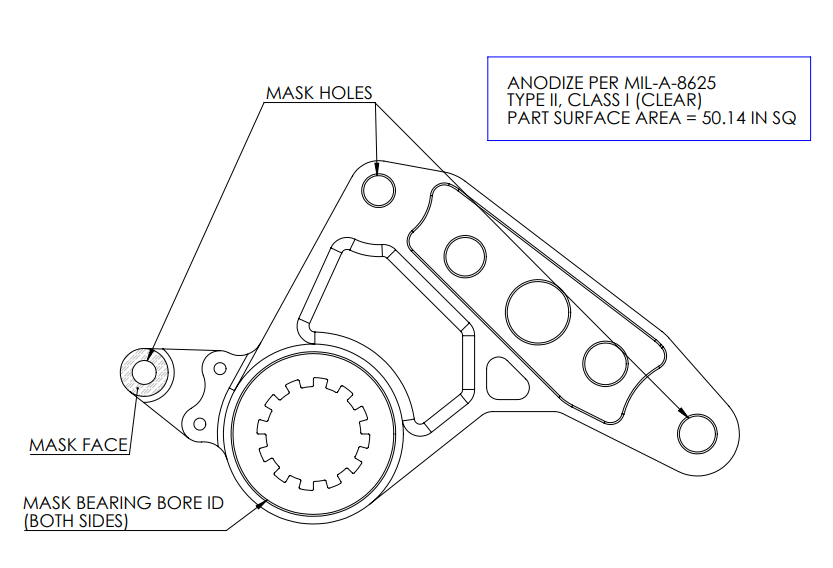
- Surface area! Your anodizing shops will love you if you put the part surface area on the drawing. This helps them compute current density and overall process time while quoting.
Closing Thoughts
Thanks for reading if you made it this far! I hope you’ve gained a more comprehensive perspective on how to design and manufacture anodized aluminum parts. A first principles understanding of the process and the coating that it forms will allow you to make good design decisions, specify the appropriate coating, and work effectively with vendors.
If you think you’ve found a mistake in this article or you have any questions about how to design anodized parts or how to specify anodizing coatings, feel free to reach out to our engineering team at support@fiveflute.com
Cheers!