There’s no faster way to damage senstive electronics or sieze mechanisms through corrosion than by allowing water ingress into your product. From consumer electronics to industrial machinery, waterproofing is an essential design skill that not only enhances the durability and reliability of products but also safeguards them against other environmental factors such as dust, and debris. This guide provides mechanical engineers with a comprehensive overview of designing waterproof products, covering the IP rating system, O-ring seals, gasket design, and actionable best practices that you can incorporate into your product design practice.
Understanding the IP Rating System
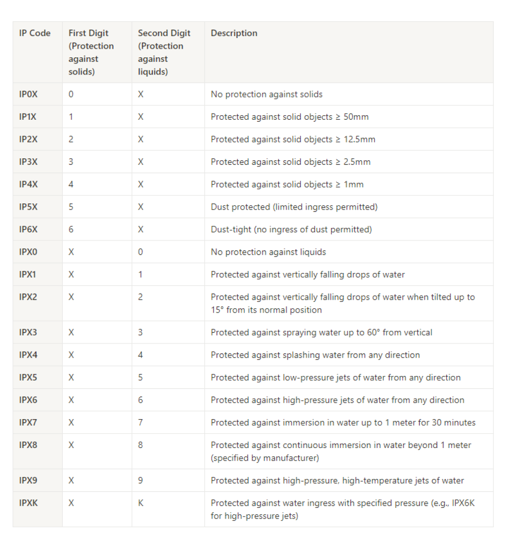
The International Protection (IP or Ingress Protection) rating system classifies the degree of protection provided against solid objects and liquids. It consists of two digits, where the first digit indicates protection against solids, and the second digit indicates protection against liquids. For example, an IP67-rated device is dust-tight (6) and can withstand immersion in water up to 1 meter for 30 minutes (7).
Here's a table that enumerates the individual IP ratings. The table provides a clear breakdown of the IP rating system, with the first digit indicating protection against solids and the second digit indicating protection against liquids. The description column offers a brief explanation of each rating level, detailing the level of protection against various types of solids and liquids. For the sake of this article we’ll be focusing on IPX4 up to IPXK, which represent increasing levels of waterproofing in a design.
Designing O-ring Seals
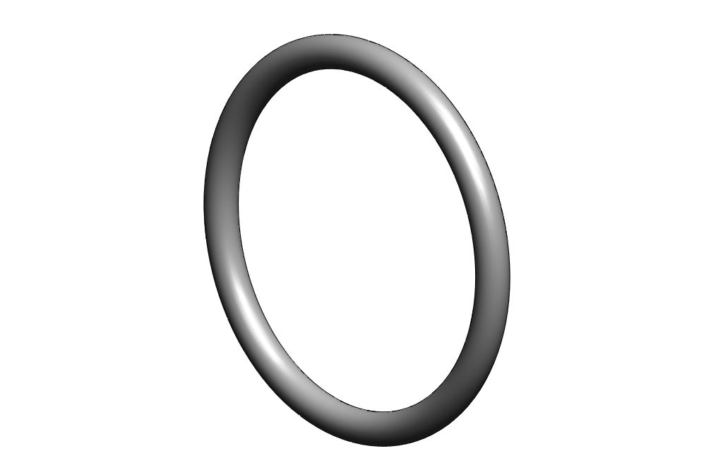
The ubiquitous O-ring is the most widely applied mechanical design pattern in sealing applications.
O-rings provide a reliable and cost-effective solution for sealing joints against leaks. Understanding O-ring design principles is essential for mechanical engineers because they are well characterized, there’s a wealth of design information readily available (Parker O-ring Handbook anyone!?), they are cheap to produce, and the design is extensible to a wide range of geometries. If you learn one thing from this article, I would want it to be O-ring design.
Basic Principles of O-ring Design
O-rings are a special class of gasket, typically with a circular cross section. They come in standard diameters, or you can purchase O-ring material on a spool for making custom lengths. The design of O-rings relies on a few fundamental principles to ensure their effectiveness in sealing applications. These principles are critical for achieving the desired performance in preventing leaks of liquids or gases between two parts. Here are the basic principles of O-ring design:
-
Seal Geometry: Seal geometry has two primary components, the gland design and the O-ring size and fit.
-
Gland Design: The O-ring seal gland is the groove or channel within which the O-ring sits. The geometry of the gland defines the degree to which the O-ring is compressed during installation.
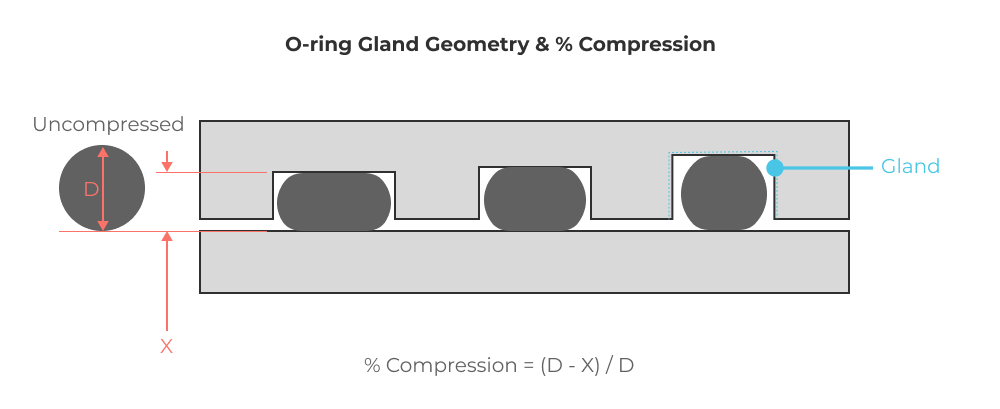
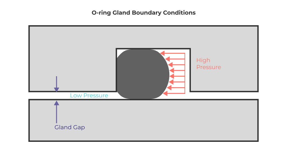
It also establishes the constraints (boundary conditions) on the O-ring when a pressure differential is generated across the seal.
In additon to the gland geometry, its important to consider the local surface finish where contact is made with the O-ring. As seal pressure increases, the importance of reducing surface roughness becomes a driving design constraint.
- Size and Fit: Proper O-ring sizing is essential for effective sealing. This includes both the inner diameter (to ensure a snug fit on the hardware) and the cross-sectional diameter (to ensure adequate compression without excessive deformation). One of the most tricky considerations is when the standard O-ring circumference does not match the effective length of the gland. Generally speaking, its OK to use an undersized O-ring that must be stretched to fit into the gland, as long as you consider the overall reduction in cross sectional area due to the stretch (remember Poisson’s ratio!). The Parker O-ring handbook has a section with charts that relate the relative stretch to cross section diameter reduction.
-
-
Material Selection:
-
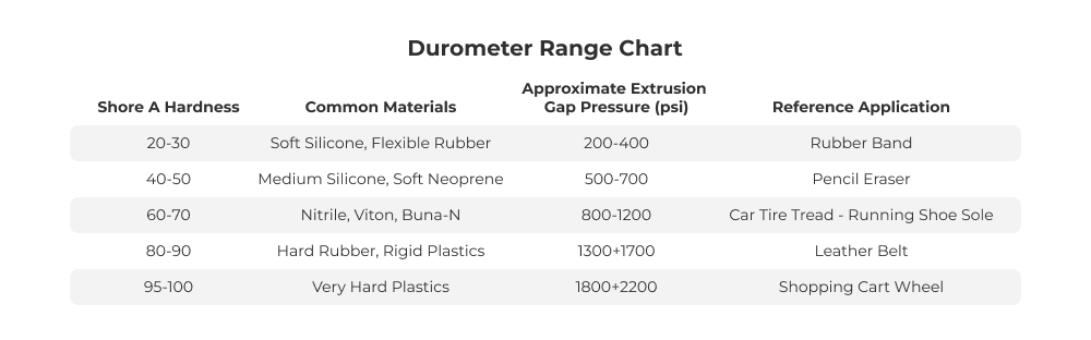
Elasticity and Hardness: The hardness (measured in Shore A units) affects the seal's ability to conform to the mating surfaces. The material must be elastic enough to allow for compression but hard enough to maintain a seal under pressure. Keep in mind that achieving IPX7 (and below) is a very low pressure sealing application. You are going to want to consider the softer end of the durometer range for these applications, particularly when dealing with plastic enclosures. In low pressure applications with compliant product housings (a phone for example), the primary design challenge is not dealing with high pressure, but rather ensuring the seal functions reliably across a broad temperature range while also considering manufacturing tolerances and applied loads. Here’s a chart you should familiarize yourself with so you begin to build your intuitive understanding of the Shore hardness range.
-
Compression Set: Compression set is defined as the permanent deformation of a material after a compressive displacement is applied at a specified time and temperature. A material with low compression set is able to return or spring back to its original (undeformed) shape after long periods of compressive deformation. Materials with a high degree of compression set tend to lose seal preload over time, making them more susceptible to failure when operating conditions and applied pressures change. Always consider compression set, especially when dealing with low durometer seals used in ingress protection applications.
-
Swell: Some materials may expand in volume as they become waterlogged. This volume increase is often associated with a reduction in hardness and a change in seal preload. Sometimes this can act to compensate for the reduction in sealing performance caused by compression set.
-
Compatibility: The choice of O-ring material is crucial as it must be compatible with the environment (temperature, chemicals, and pressure) in which the O-ring will operate. Common materials include Buna N, Nitrile Rubber (NBR), Fluorocarbon (FKM), Silicone (VMQ), Viton, and Ethylene Propylene Diene Monomer (EPDM). For the sake of this article we’re mostly concerned with water and air sealing so compatability is often a non-issue.
-
-
Operating Environment:
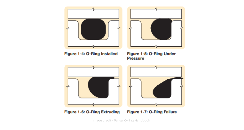
- Pressure Range: In the majority of waterproofing applications the pressure differential that an O-ring seal must accomodate is relatively low. O-rings can easily function reliably in 5000+ psi pressure environments (compared with the 10 meters of water or 14.2 psi usually associated with IP68 rated products). In many cases, you’ll be designing seals that you don’t want to have to preload very much. The art and science of low pressure sealing involves thinking though how to get reliable seal performance at low preload with relatively compliant components. This contrasts high pressure seal design in hydraulic applications when you have extremelly stiff flanges to provide O-ring compression when assemblied.
In general, as pressure differential increases, so should the hardness of the O-ring material. This helps prevent O-ring extrusion under load. However, for low pressure seals, the most critical design challenge is ensuring enough preload across the entire seal at relatively low clamping loads. A lack of local stiffness at a seal flange can compromise seal performance. Similarly, it can be difficult to achieve a large % compression because of component strength and stiffness. This can make designs susceptible to failure when manufacturing tolerances widen or change (can you say mean shift anyone!?).
- Temperature Range: The O-ring material must be able to withstand the minimum and maximum temperatures of the application environment without degrading. Be sure to consider both the hot end and cold end of the temperature range with regard to bulk volume, hardness, and compression set changes. The Challenger explosion is the classic case of degraded O-ring performance at low temperatures.
- Dynamic and Static Applications: The design considerations vary between dynamic applications (where there is movement, such as in pistons or rods) and static applications (where there is no movement, such as flanges). Dynamic applications may require materials with higher wear resistance and seals with lower pressure rating. The Parker O-ring handbook has a fantastic section that reviews design considerations for dynamic seals, which we will largely ignore during the remainder of this article because the vast majority of product waterproofing involves static seals between two or more enclosure components.
-
Installation Considerations: Because O-ring seals require component deformation when assemblied, there is significant risk of damage during the assembly process. You should consider the following items when designing seals for assembly.
- Lubrication: In addition to increased sealing performance, using an O-ring grease (I like Dow Corning Molykote 55) can prevent damage during installation and throughout the life of the seal caused by friction and wear. Remember that the lubricant must be compatible with the O-ring material and the media being sealed.
- Clean surfaces: Low durometer seals can be easily cut and damaged if the gland and sealing surfaces are not clean and burr free. I’ve made this mistake with an engine oil system and it was the first $10,000+ mistake in my career. Although small cuts in seals may not ruin low pressure seal performance, in IP68+ applications surface quality during assembly becomes critical.
These principles embody a wide array of constraints, but we can boil it down to a simple goal. You want to ensure that the seal you design is capable of reliably handling the peak pressures expected during its lifetime in the harshest operating environment possible with the most adverse allowable manufacturing tolerances and material performance.
Radial O-ring Seal Design
Radial O-ring seals are used when the sealing surface is parallel to the O-ring’s axis, such as the seal between a shaft and it’s housing. The gland can either be machined into the housing such that the gland floor contacts the outer diameter of the O-ring, or machined into the shaft such that the gland floor contacts the inner diameter of the O-ring.
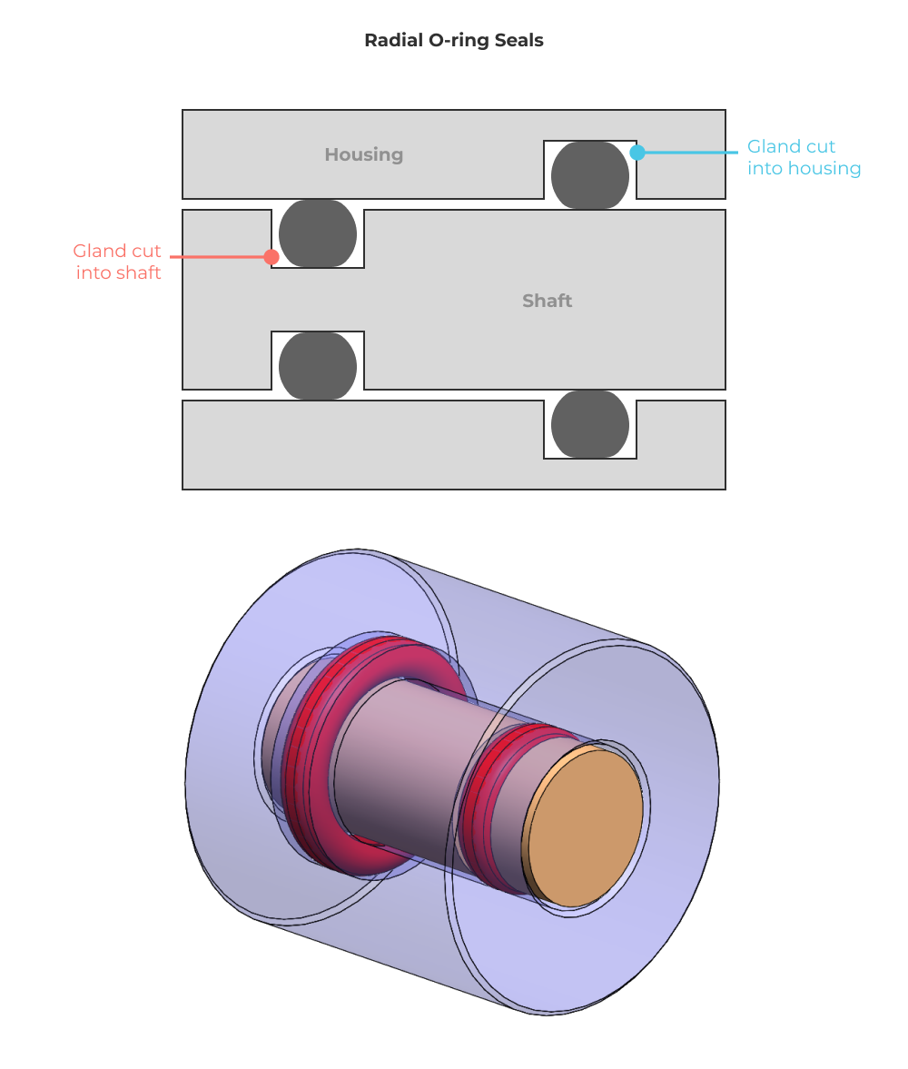
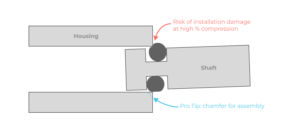
Radial O-ring seals can be especially difficult to assemble when there is significant O-ring squeeze. The shaft and housing must be pushed together with the O-ring already installed, which can lead to shearing and extrusion of the O-ring. For relatively low pressure waterproofing applications I like to aim for the lowest possible O-ring compression that I can reliably get away with, in order to avoid assembly difficulties.
Axial O-ring Seal Design
Axial O-ring seals are used when the sealing surface is perpendicular to the O-ring’s axis, such as the seal between two clamshells of an enclosure. The gland can be machined into either housing depending on assembly order and maintenance concerns.
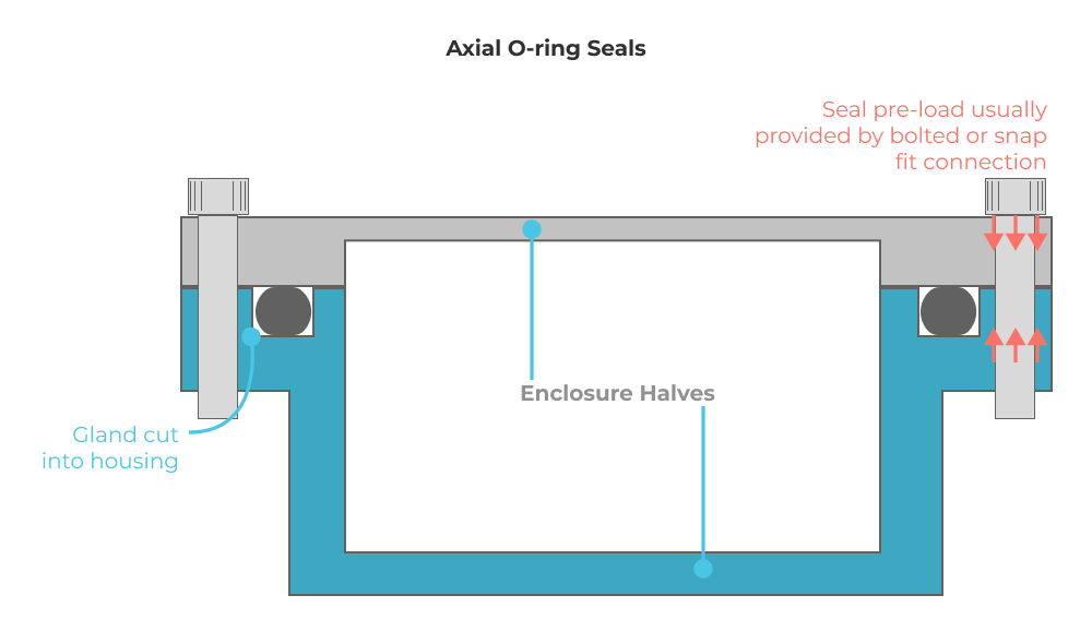
In axial seals, the O-ring compression is a direct function of the load applied through fasteners (or other means of clamping between faces). This gives you a great deal of control over seal preload, but can also cause a larger range of performance variability across a population of devices. Just like in traditional gasket design, axial O-ring seals can cause bending loads in enclosure components due to the non-uniform load distribution caused by fasteners. The deflection of enclosure components can then cause variable preload and degraded sealing performance across the length of the seal.
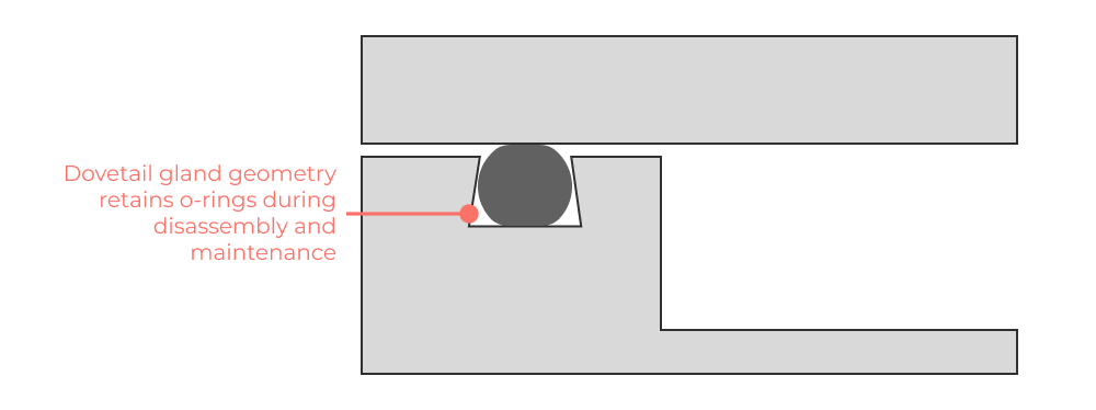
Pro Tip: One useful technique in axial seals is to machine a dovetail gland geometry. This allows the O-ring to be captured in the gland, thereby preventing unintended disassembly during maintenance. Be sure to consider how much groove volume is needed to support O-ring deformation as a function of compression %. Check out Harvey Tool to see available cutter geometries for your designs.
Designing Gasket Seals
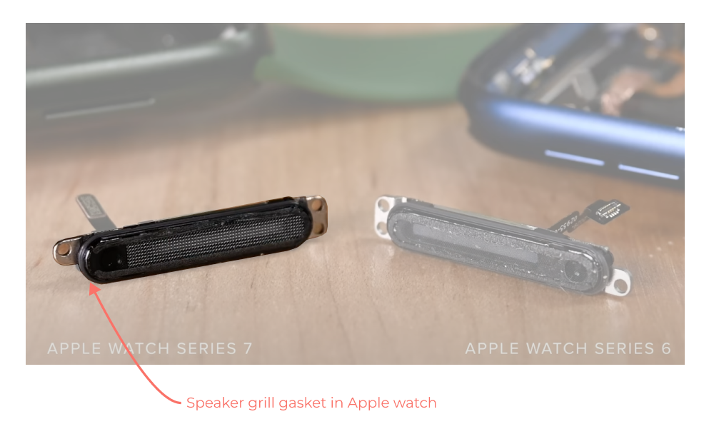
Gaskets are used in a wide variety of products and applications, but consumer electronics products provide demonstrative design examples. The iFixit teardown of the Apple watch has a great feature on ingress protection that shows the gaskets on the speaker grills.
What are gaskets?
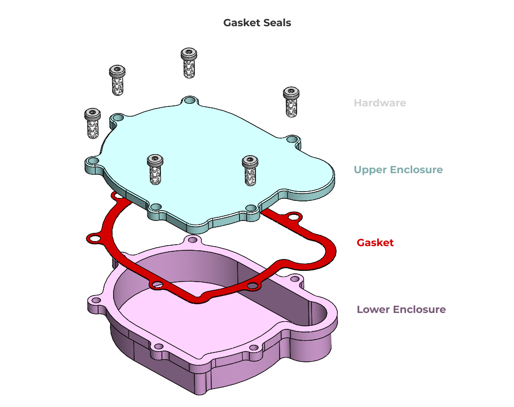
Gaskets are a general class of axial seal formed by the clamping (and sometimes permanent deformation) of a sealing material. For the sake of product waterproofing applications most gaskets are designed using either thin sheets of rubber material, or through the use of overmolded rubber on injection molded components. The basic design principles apply to both approaches so we’ll discuss the general concepts first before getting into application specific recommendations.
How do they work?
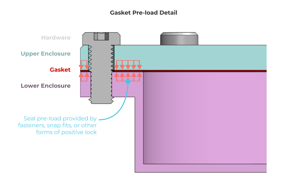
Gaskets work by applying a clamping load to a sealing material. This sealing material gets compressed locally, creating one or more sealing faces between opposing components. Gaskets have sealing faces along a flat plane, or across a complex 3D surface (more common for gaskets that seal injection molded components with complex parting lines).
Gasket preload control
Effective gasket design is about ensuring relatively uniform pressure distribution along the gasket faces. Local areas of reduced pressure are effectively “weak points” where leaks may originate.
As a designer you should try to build your intuition around the stiffness of enclosure components, and how their relative (local) compliance may impact seal preload. Using our example enclosure, we can highlight areas where the pressure distribution on the gasket might be compromised because of the load path between fasteners.
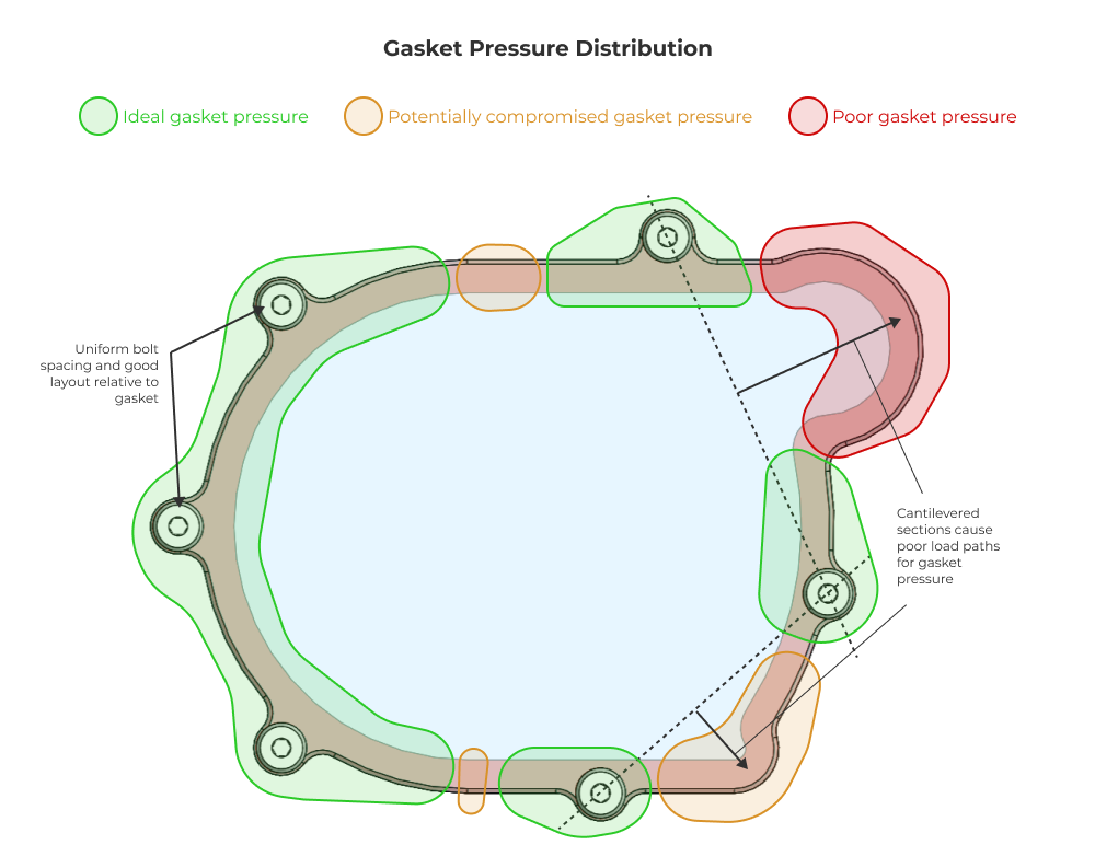
The key element is to determine those areas of reduced component stiffness that may result in reduced gasket preload. These are the areas where seals will fail as pressure differential increases. You can of course build your intution for this, or you can run finite element analysis.
- Material Selection: Gasket materials vary depending on the application, ranging from rubber to metal. Factors such as compressibility, temperature resistance, and chemical compatibility must be taken into account.
- Surface Finish: Achieving a smooth and flat mating surface is crucial for gasket sealing. Surface roughness and imperfections can lead to leaks. Machining or grinding may be necessary to achieve the desired surface finish.
Wet Gaskets & RTV
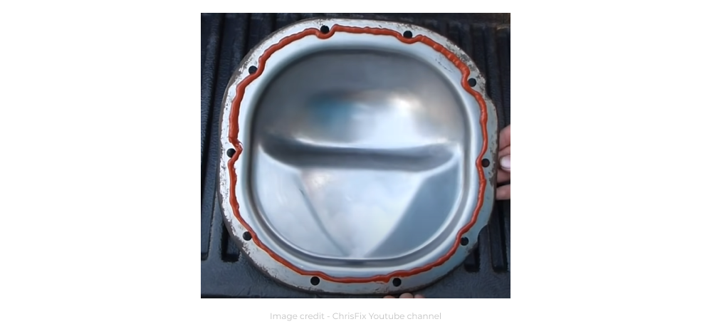
One of the most used gasket types is a RTV (room temperature vulcanizing silicone). This is a “wet gasket”, meaning it is applied like an adhesive, but it sets in place under load. Here’s a great example video showing RTV application for a rear differential gasket. In general, because RTV is vulcanizing in place after being squeezed to final dimension, it is best suited for relatively low pressure sealing applications. It’s a pain in the butt to disassemble, so don’t consider it a viable solution for frequently serviced items or consumer electronics. That said, it’s easy and it works to keep dust, debris, and water out of critical machine component interfaces.
Best Practices and Miscellany
Managing seal preload and pressure distribution
I wanted to highlight a few quick design tips regarding seal pressure control. For many low pressure seals, soft durometer material is used and limited clamping force is available. Here are some techniques for controlling seal pressure.
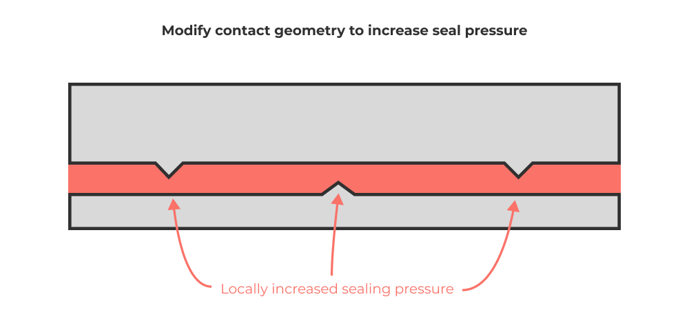
Reduce or modifying contact area to increase pressure
Adding ridges or other changes in surface geometry can help locally increase the seal pressure.
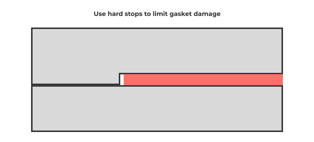
Mitigate gasket damage with hard stops
If soft gaskets are over compressed they can be damaged, thereby compromising sealing. Consider using hard stops to limit the allowable compressive displacement of the gasket.
Dealing with internal pressure changes
Remember that for a sealed device, the change in internal pressure due to temperature change (think ideal gas law) may be the dominant design constraint. Don’t overlook this! A reduction in internal air pressure can cause ingestion of water by increasing the pressure differential across the seals.
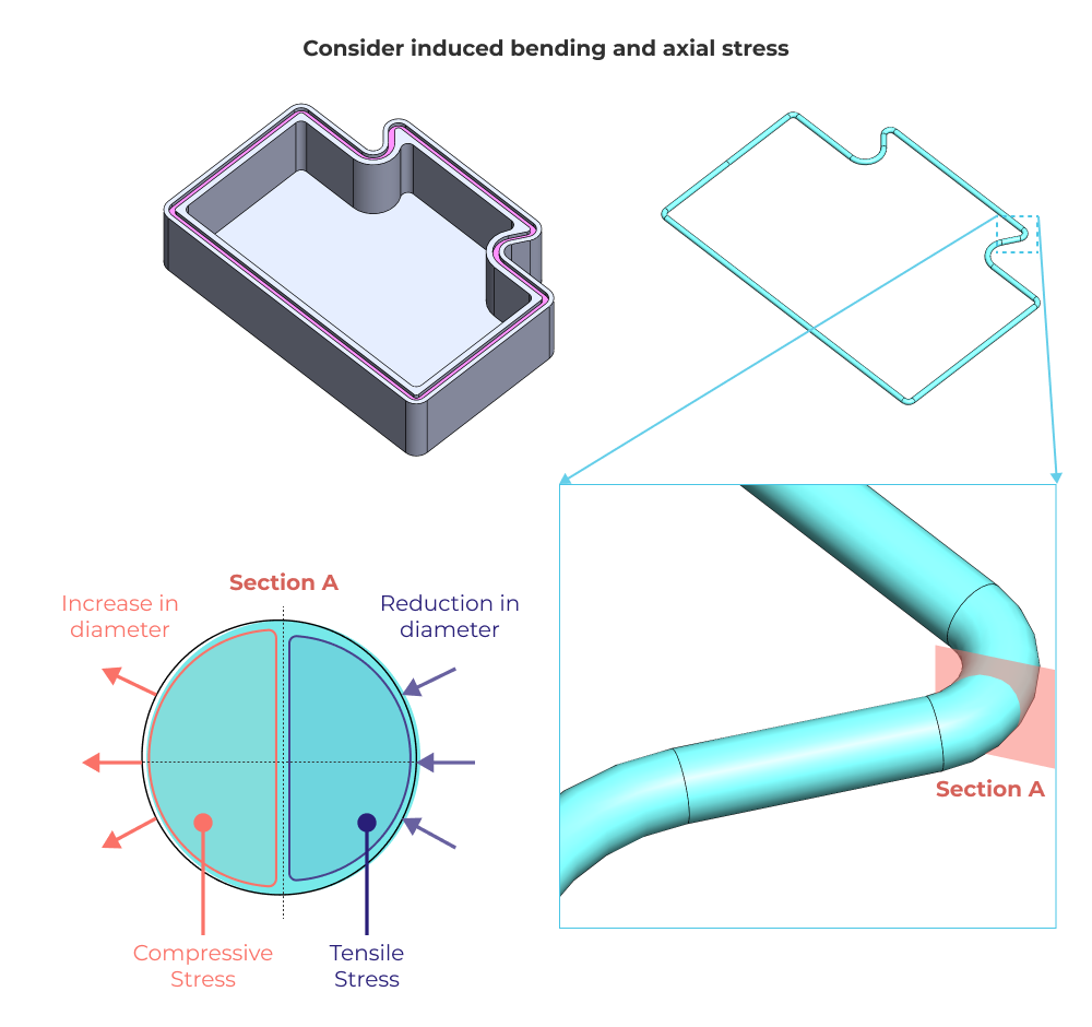
Beware of Local Deformation of O-rings
For axial enclosures using O-rings, you want to pay attention to the path that the O-ring groove makes. Extremely tight corners will add stress to the O-ring. Remember that any axial or bending stress induced in the O-ring will change the cross sectional area, thereby impacting sealing performance.
Temperature and Durometer are Linked
Richard Feynman has an outstanding demonstration of the impact of temperature swings on an O-ring’s durometer, elasticity, rate of spring back and compression set. Always remember to design for your worst allowable operating conditions, including cold weather.
Potting and Conformal Coatings
Remember that air contains mosture, including the air sealed inside your product during manufacturing. When designing waterproof products, consider how changes in pressure and temperature can cause condensation of this trapped moisture on sensitive electronics. Conformal coatings and potting are simple and reliable methods to prevent small amounts of condensate from interfering with electronics or causing corrision over time.
Overmolded Gaskets
Overmolding isn’t just for aesthetics. Consider how you can use overmolded rubber (such as TPS-SEBS) as a functional gasket. Aside from assembly cost, one advantage of this method is the reduction in leak paths. Overmolding effectively bonds one of the seal interfaces, thereby reducing the total surface area that needs to be sealed via gasket preload.
A Note on the Importance of Testing
FEA is very challenging with large deformations of non-linear materials like rubber. Designing seals by analysis only is a very risky proposition. You should consider very rigorous testing across a population of devices if you want to ensure reliable sealing performance in your designs. It’s costly, but not as costly as product failure, rework and returns.
Understanding Shore Hardness and Young’s Modulus
One of the hardest parts of seal design is determining the effective stiffness of the seal and the target compression %. In general, there is a correlation between Shore hardness and Young’s Modulus. In practice this can be hard to determine and often must be determined experimentally. Below you can find a chart showing this relationship.
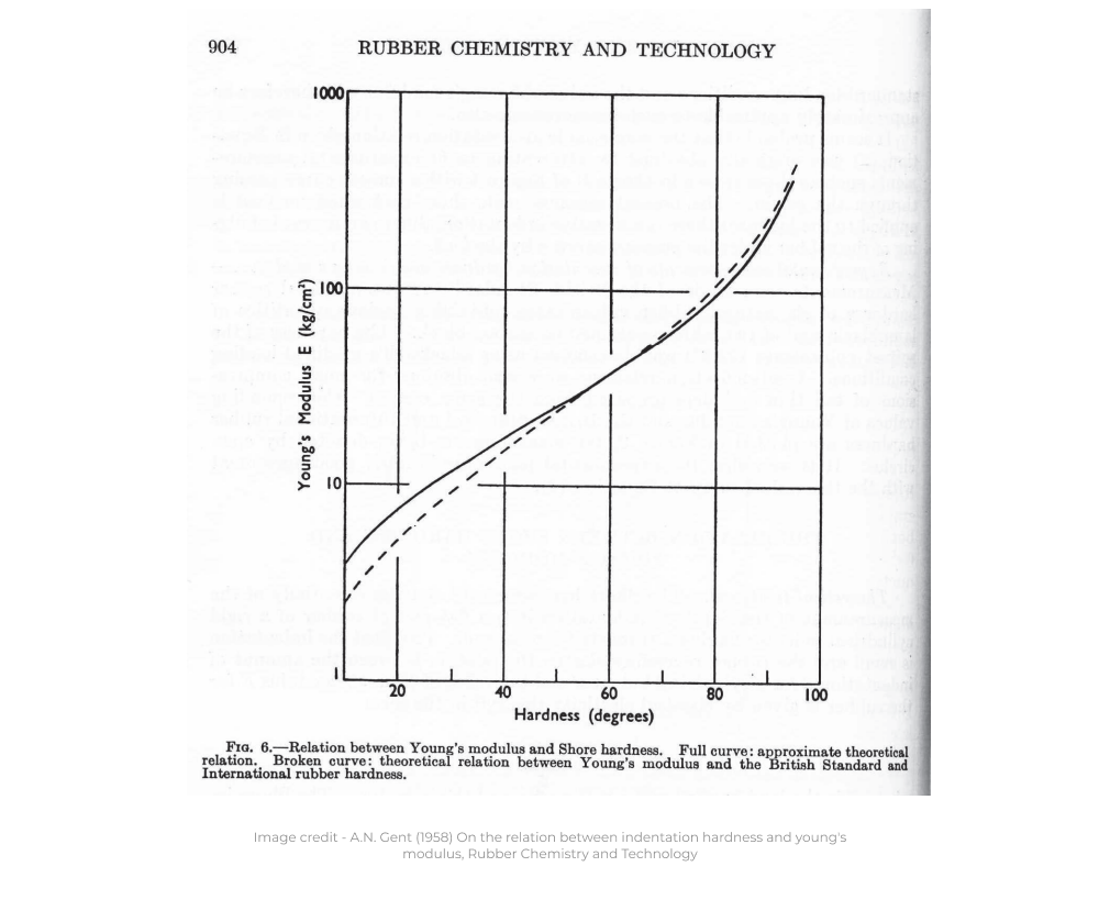
This reddit thread elaborates on this relationship for elastomers (warning: use at your own risk!). MATWEB also has a great page relating the various hardness scales. Rubbers and elastomers have non-linear and viscoelastic behavior that is generally pretty weird and challenging to design for, so be conservative and test thoroughly!
Conclusion
The ability to design waterproof products is 80% science and 20% art, but that’s why it’s both valuable and fun. As an engineer you should understand how to design radial and axial O-ring seals, gaskets in a wide range of geometries and applications, and an overall understanding of elastomeric materials and how to apply them in product design. I recommend you keep the Parker O-ring handbook at the ready and review it thoroughly. Material performance and tolerances are often the X-factor in seal designs, so be sure to implement both analysis and testing that are conservative and representative of real world usage. If you can manage all of that, you’ll end up with a reliably waterproof design.
Good luck and thanks for reading!