Motivation - What problem are we solving?
Design for manufacturability (DFM) and design for assembly (DFA) (grouped together as DFMA) pose a simple question to product designers and engineers. How can we design products such that the cost of manufacturing and assembly is minimized? Like many problems in engineering, DFMA encompasses a large problem space where optimal solutions require careful balancing of engineering and business tradeoffs. This engineering guide will focus on balancing those tradeoffs by developing a foundational understanding of the following:
- How development cost evolves during product design
- Where cost comes from in manufacturing and assembly
- DFMA frameworks and guidelines for designers
- Rigorous methodologies you can apply to high volume product design
Where does product development cost come from?
Before diving into DFMA, it can be helpful to take a look at product development costs more generally. Every product development effort is unique to the team and product being developed, but there are some general trends worth understanding.
Design is iterative and requires multiple rounds of prototyping
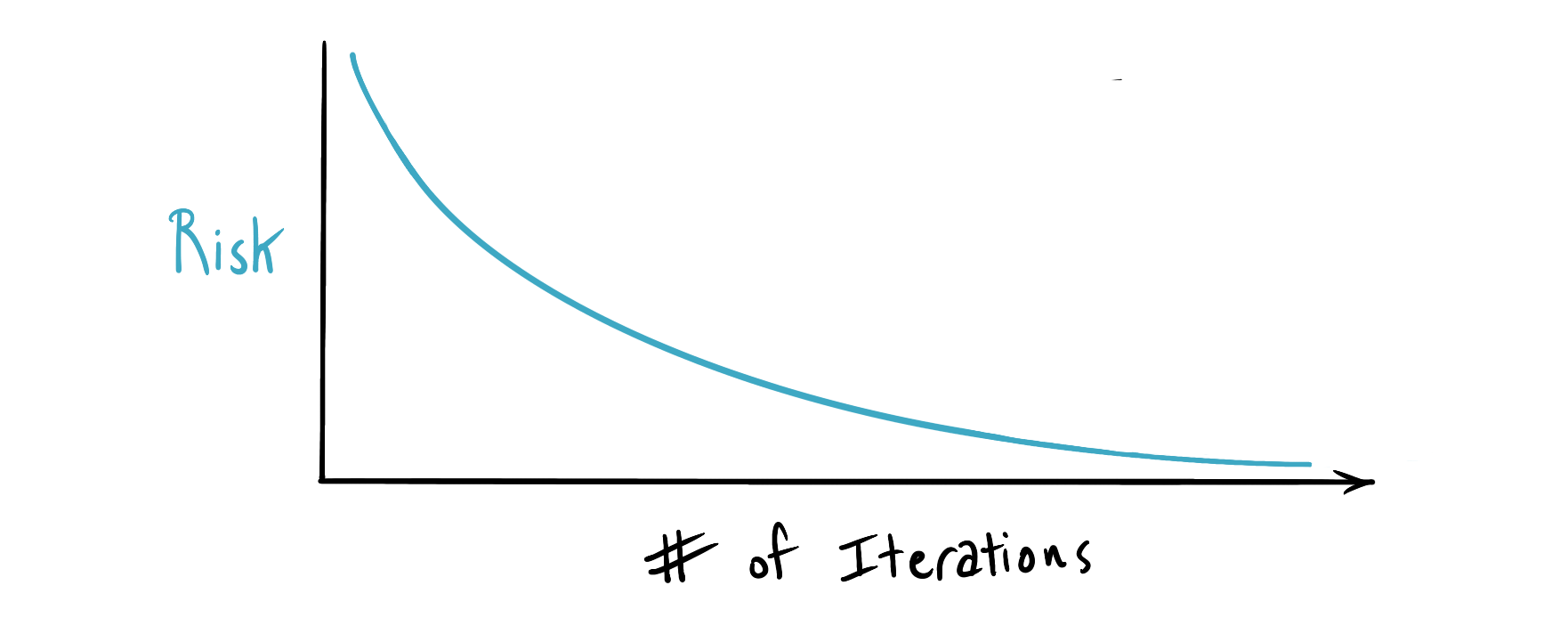
Good technical development is often characterized by a risk reduction approach. Early prototypes and analysis retire architecture risk and set the direction for a product. Subsequent iterations increase the fidelity of the design, while further constraining the shape of the final product.
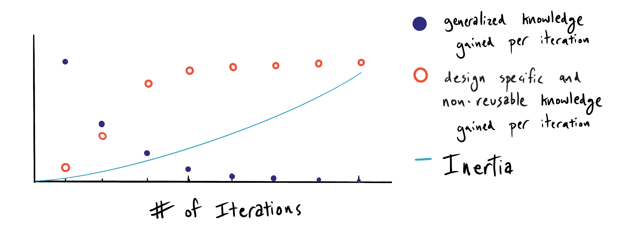
Inertia Builds: Risk is traded for specific knowledge and design stability
The process of prototyping to retire risk develops specific knowledge within the design team which is often only useful in the context of that specific product. This process introduces inertia into the design. Inertia is the confluence of cumulative development effort, sunk costs, design specific knowledge and non-reusable or generalizable work effort.
Inertia is the basis of non-linear costs in product development
As more prototypes are developed and the design team begins to see a clearer picture of the final design, inertia builds. Making a large scale change late in the development process has a non-linear impact on cost because of the inertia of the design. In other words, recovering from a late stage setback (when inertia is high) requires more effort than recovering from an early stage setback. One (nerdy and awesome) way to think about this is to imagine that inertia vs iterations is a convex function. A setback to the project or a change of direction in the design requires you to go back some number of iterations to recover. The cost of recovery can be thought of as the definite integral of the inertia function between the number of iterations you are traversing between.
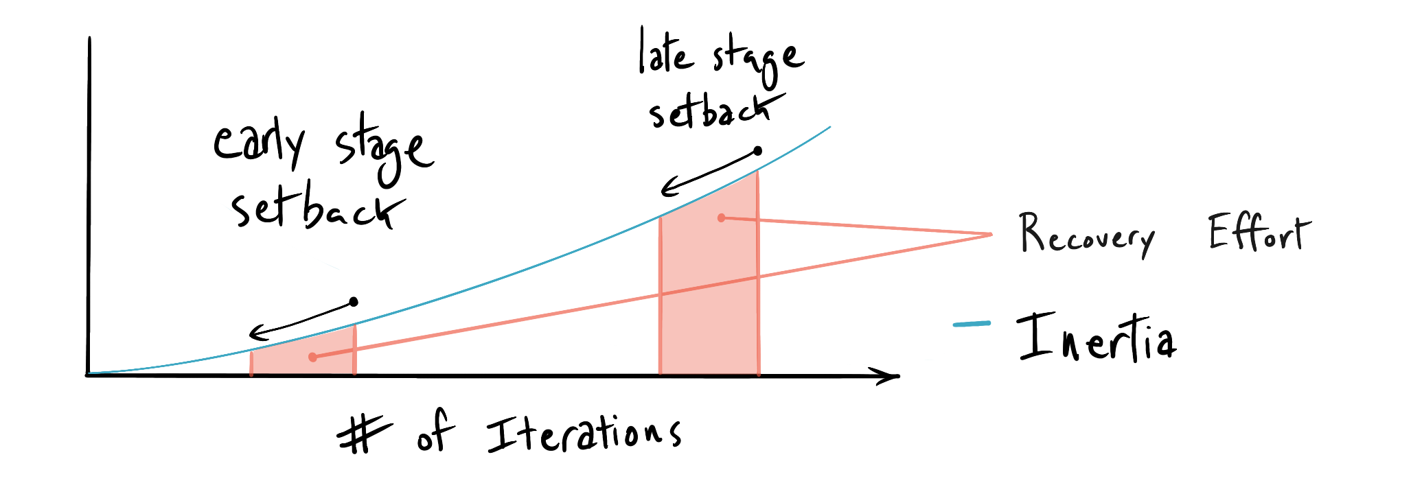
What's the point of this overly nerdy demonstration of inertia in product development? The point is that no matter what you do, or how many people you have working on a project, the cost of late stage design changes (for any reason) will be roughly an order of magnitude higher (or more) than the cost of design changes when architecture is still flexible and the design is not stable.
What does this mean for DFMA?
The more risk and complexity you have in manufacturing and assembly, the earlier in the product development process you should incorporate DFMA. The goal is to identify and solve DFMA problems before inertia builds, when the relative costs of changes to product design are lower. Many of the design changes espoused in popular DFMA frameworks (ex: Boothroyd Duherst) such as combining several parts into one, impose significant engineering costs when system complexity is high. Even for high volume products, this engineering cost may outweigh the marginal benefit of reduced assembly cost per unit. No methodology should be used outside of the broader context of the full product development cycle.
How to start?
The first step in minimizing any function (cost or otherwise) is to identify and characterize the function itself. What are the sources of cost in your designs? Even with imperfect information, attempting to identify them can be a very informative process. We recommend building a manufacturing and assembly diagram for the whole product, sometimes called a process flow. This does not require special software and does not need to be a very formal document for it to be valuable. You can start by building a simple block diagram of the manufacturing and assembly process that starts at some level of “raw” or base material and ends with a finished product. You should be mapping out the following:
- Material sources - ex: extruded 2024-T4 aluminum tubing from Alcoa
- Primary manufacturing processes - ex: die casting
- Secondary manufacturing processes - ex: coatings, platings, and surface treatments
- Cosmetic processes - ex: powder coating
- Sub assembly processes - ex: bearing press. These may require fixtures or tooling which you or your manufacturing partners may be required to develop
- Final assembly processes - ex: incorporation of sub-assemblies or modules into the final product
- Packaging processes
An example process flow, focusing on a single component of a car roof rack, is shown below.
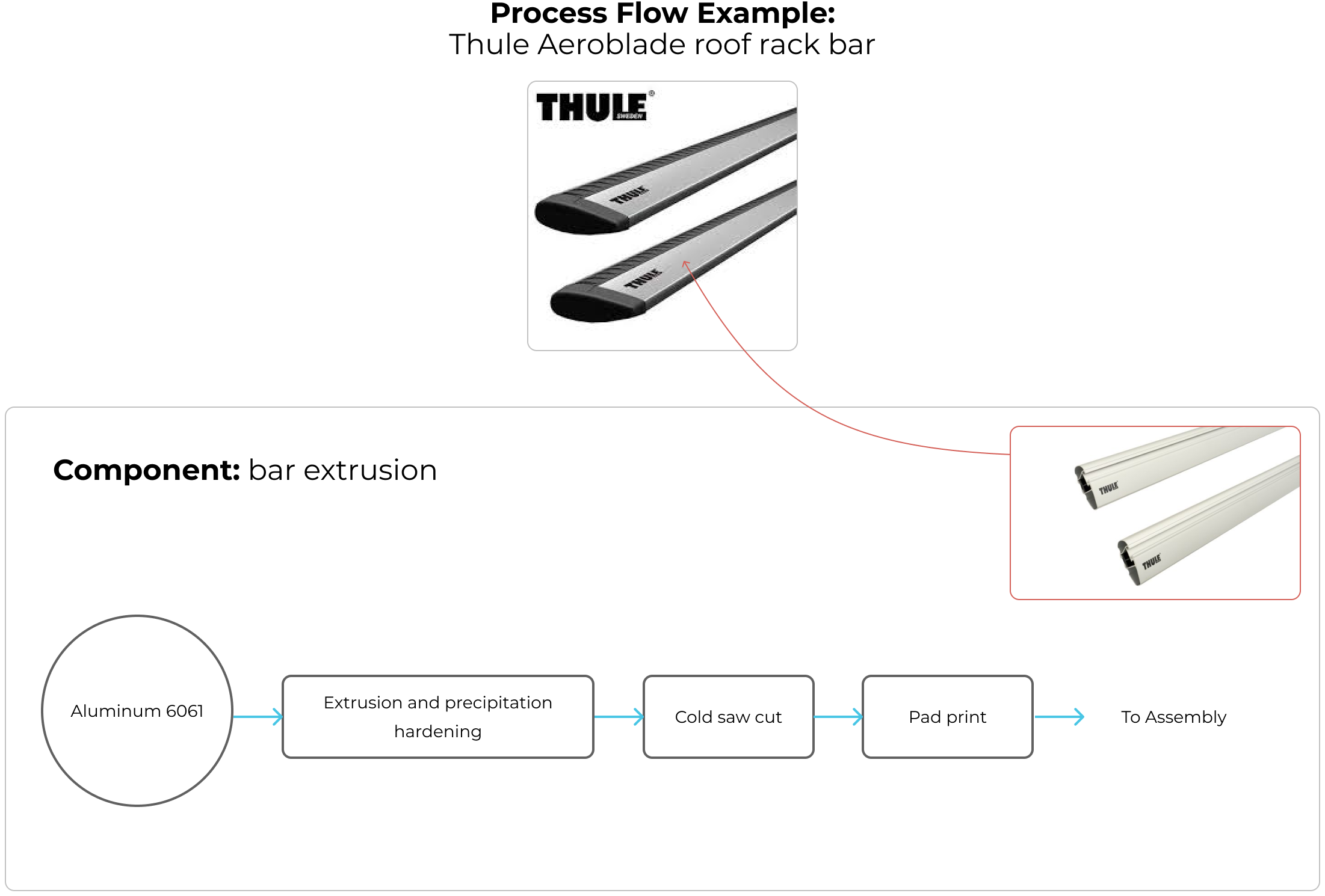
By forcing you to think through all manufacturing and assembly procedures in your design, the process flow diagram helps you identify what aspects of your design will be most expensive, risky, or require further engineering effort. Constructing a preliminary process flow diagram can help you avoid the mistake of locking in expensive manufacturing operations while the design is still flexible and development inertia is low.
Note: Assembly failure mode effects analysis (aFMEA) can be very useful at this stage as well as a means of rigorously interrogating the process flow.
Implementation
Once you have a feel for the process you are optimizing, you can start with some general guidelines. Applying these might not be straightforward, and may require large design and manufacturing changes. Because this is more of a lateral thinking than linear thinking process, consider conducting a DFMA redesign brainstorm focusing on the key sub-components and assemblies that you identified in the process mapping and aFMEA exercises. To seed these brainstorms, you can use the following general guidelines for assembly and manufacturing.
Design for Assembly Guidelines
Reduce Part Count. The highest value step to reducing cost in assembly is to minimize the total number of parts being assembled. Fewer parts will reduce cost across the whole project; in manufacturing, scrap, inventory, handling, assembly and shipping. The lowest hanging fruit for reducing part count usually involves combining two or more parts of similar materials into a single component. Because this often requires manufacturing process specific knowledge, it is a good idea to invite a group of brainstorm participants with differing manufacturing backgrounds and knowledge.
A good case study of this kind of savings is the collaboration between Vitamix and Carbon 3-D. Essentially you should be looking for groups of contiguous parts that are fastened, glued or welded together that can be combined into a monolithic structure via some net near shape process (ex: casting, injection molding, etc...). To illustrate this we can look at the following example that compares two designs of an automotive steering knuckle (sometimes called a front upright). One design is fabricated and welded, while the other is cast and post machined.
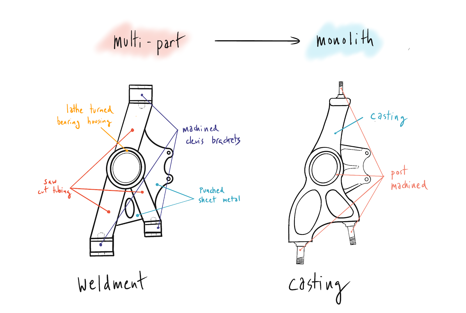
Based on unique part count alone, it is obvious that the cast component will be cheaper at sufficient volume to amortize the tooling cost.
Reduce Assembly Complexity. We can break down assembly complexity into a few key drivers.
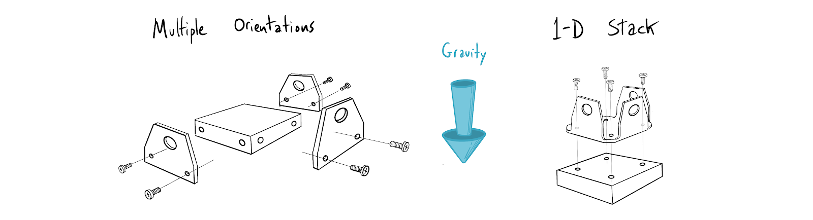
- Assembly orientation. An assembly with parts that must be combined in numerous orientations will be more costly than a straightforward top down (“pyramid” style) assembly. Whenever possible, simplify assembly operations into a 1-D stack. This allows the stacking operation to take place parallel to gravity, leading to easier and more accurate fastener and component insertion.
- Dependencies. Assembly dependencies complicate the build process. Reducing them can reduce the cost of scrap and rework on the line while allowing more process parallelization during assembly. Lets consider a hypothetical comparison between a serialized assembly process with order of operation dependencies in assembly and a parallel process with independent assembly steps. In this scenario there are four unique parts.
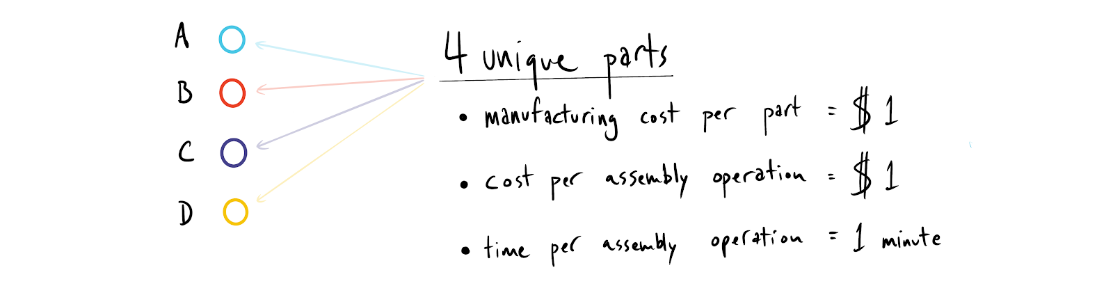
In both processes the final assembly is composed of one of each unique part. The manufacturing cost per part is $1 with a $1 cost per assembly operation. Lastly, assume the time per operation is always 1 minute. Now let’s compare these two processes by mapping them out on a Gantt chart and looking at the cost of scrap during the process if there is a problem during any particular manufacturing operation.
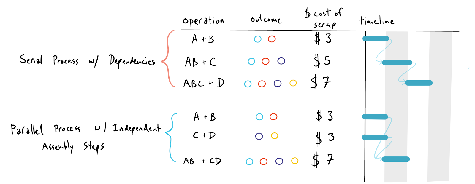
Although this is a relatively simple example, there are some interesting things to take away. Given the same final COGS and assembly cost, the parallel process without dependencies is 33% faster per unit. Additionally, assuming a uniform distribution of failures requiring scrap during any assembly operation, the average cost of a defective operation is 13% lower ($4.33 vs. $5.00 per defective operation). Removing assembly dependencies made assembly both faster and cheaper.
- Insertion or mating difficulty. Simply put, parts should be designed to fit together easily. This is a large topic that we can’t give full treatment in this guide, but there are many design changes that can be made to facilitate assembly automation and self alignment. At some point you need to fill in your imperfect information and begin designing for a particular manufacturing capability. Talking to manufacturers early is essential.
- Reduce fasteners. Removing a fastener entirely will obviously reduce assembly cost, but it should be done with a good understanding of how product performance will be impacted. One need only look at early 2000s Ford and GM vehicles to find broken plastic door panel clips all over the place. The principal difficulty of DFMA is reducing cost without impacting performance. For more information on fastener design check out the Five Flute guide to fasteners and bolted joint design.
- Design for self fixturing. Features can be added into parts that allow them to self align such that additional assembly fixtures can be eliminated. There are a number of different design techniques that you can employ to obviate the need for alignment fixtures and jigs, which we will briefly discuss below.
Tabs. Particularly useful for fabricated or glued structures using 2-D or planar manufacturing methods like laser or waterjet cutting, tabs allow accurate registration between parts before gluing, welding or fastening. A few examples are illustrated below.
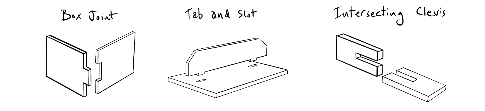
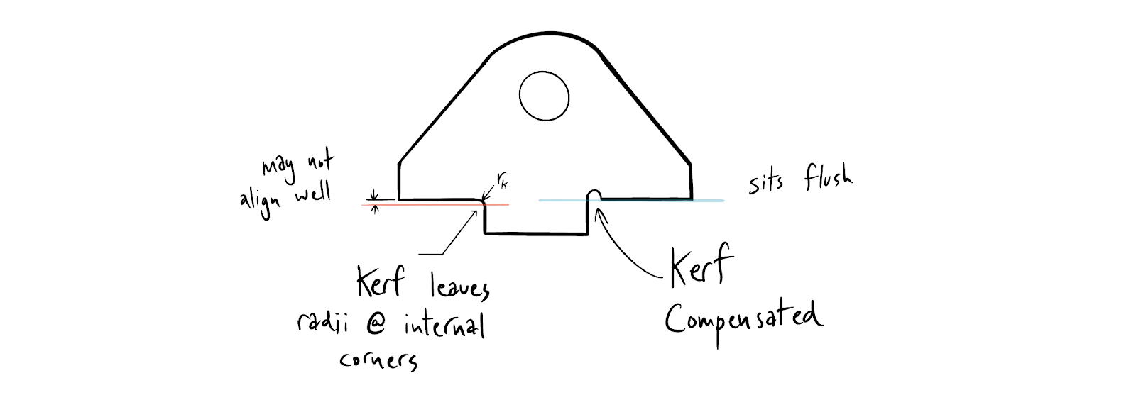
When using this method, remember that internal corners on tabs and slots may have a small kerf radius that must be accounted for to ensure accurate alignment.
Alignment pins. Dowel pins, tapered pins and diamond pins can be used to locate critical components relative two each other without external fixtures or jigs. Take care to avoid over-constraint, binding, or other assembly interference difficulties when designing in alignment pins.
Cleco Fasteners. Cleco fasteners and other temporary fasteners leverage existing hole features for component alignment. They can be installed temporarily to ensure overall alignment and fixturing, and then replaced by permanent fastener placement.
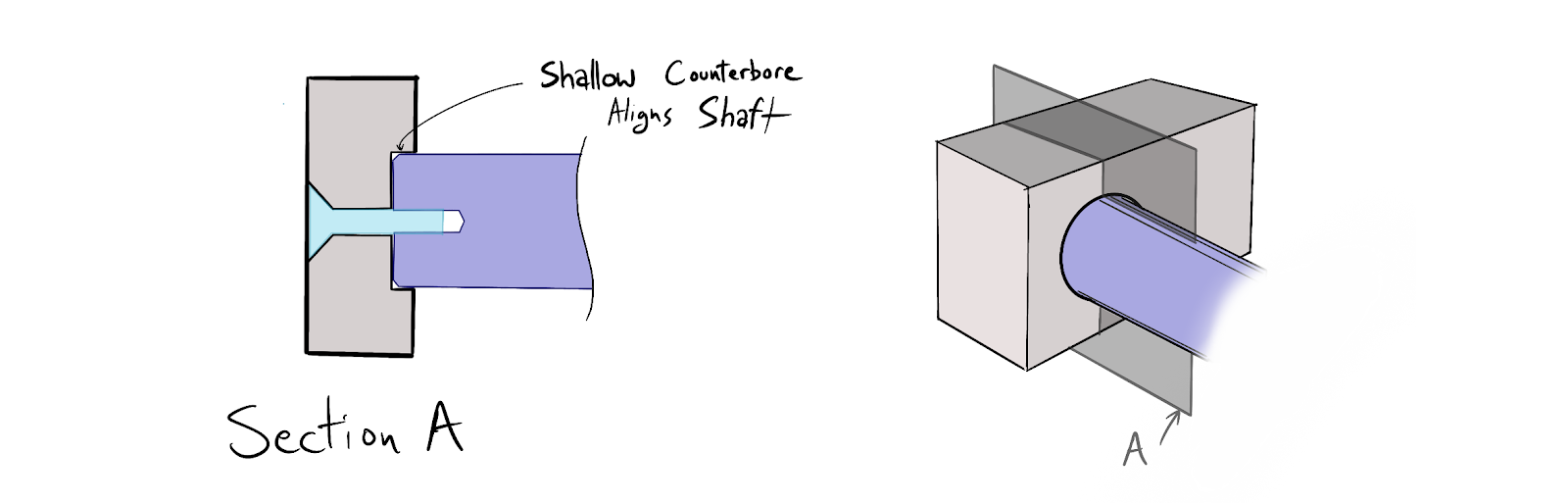
Alignment bores and bosses. Shallow alignment bores can help locate shafts and other critical components accurately while speeding up assembly time. These features can be machined or molded into components, ensuring high accuracy relative alignment at extremely low cost.
Design for Parts Handling. In volume many parts will be auto fed with vibratory parts feeders. If parts can hang up or become entangled they may jam parts feeders. If possible, avoid creating hooks and undercuts that may entangle parts together when stored in bins.
Manual handling difficulty can arise from sharp points and corners that can cut line workers. In general, hard to grip geometry, and sticky or flimsy components require more care to place correctly. This leads to slower assembly times, more mistakes and scrap, or both. Slower handling is more costly handling, so consider designing in alignment features or tools that enable assembly with large tolerances on insertion accuracy.
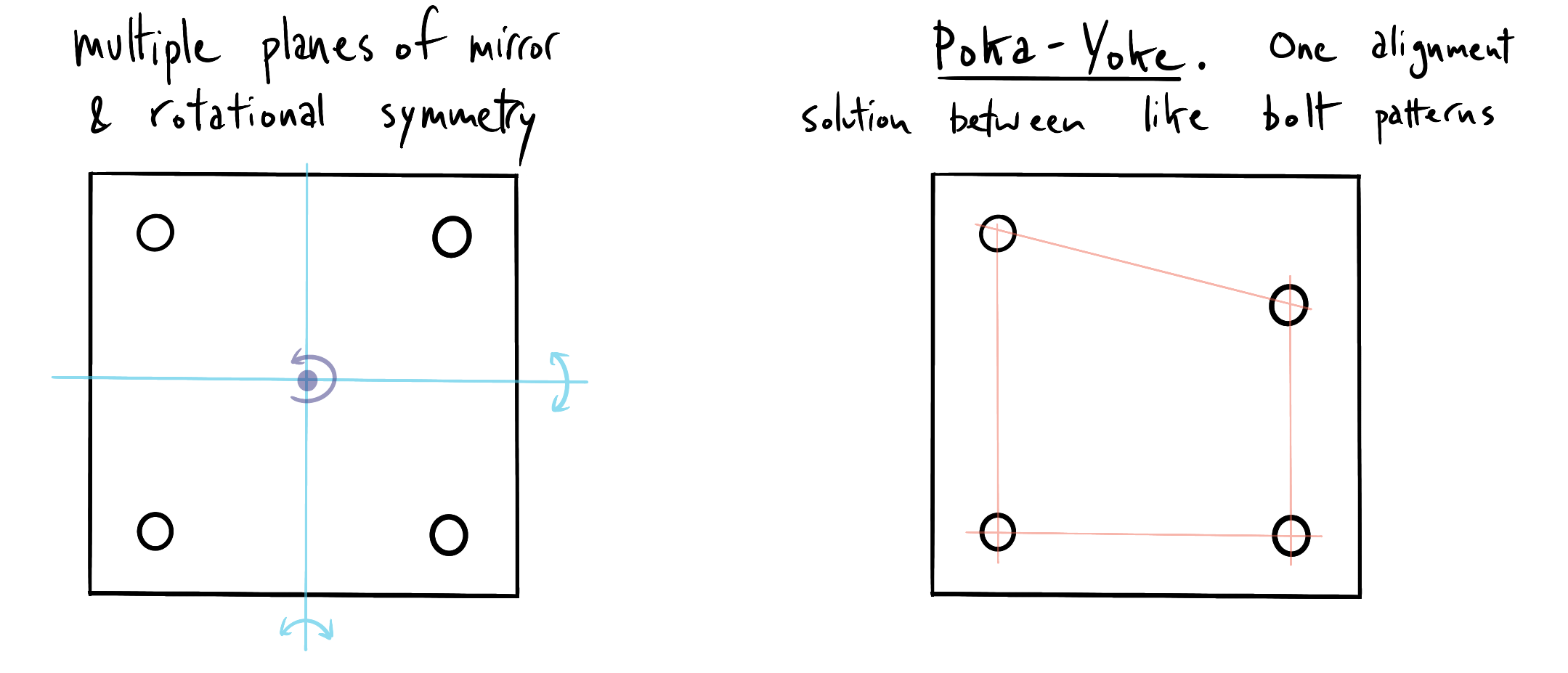
(Inadvertent) Error Prevention. You may have heard the term ‘poka yoke’, which is a Japanese term that roughly translates to mistake proofing. Poka yoke is a design technique that uses asymmetry to enforce compatible assembly configuration and eliminate incompatible configurations. Consider the bolt pattern example below that ensures feature alignment across two components.
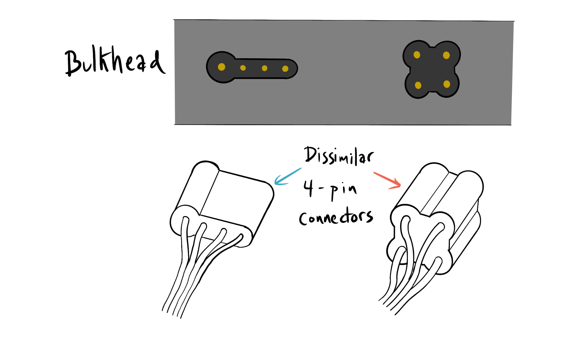
In addition to poka yoke, it is also a useful practice to make unique assembly configurations across multiple parts. The most common implementation of this technique is with cables and connectors. If two cables share the same number of wires/pins, they should have different connectors. This prevents connector mismatches during assembly.
Standardize Components and Fasteners. Standardizing on a few types of fasteners limits the number of unique tools required during assembly. Standardizing components limits the complexity of inventory and parts handling before assembly.
Design for QC. For parts that have critical alignment or installation functionality that must be verified during assembly, consider designing in methods for validating their proper placement. One simple method is to create reference geometry or assembly datums that can be checked with go/no-go gauges. The goal here is to reduce the quality check from a qualitative, judgement based procedure to a binary pass/fail criterion that can be executed quickly and reliably.
Design for Manufacturability Guidelines
Reduce Unique Part Count and Standardize
The highest value step to reducing cost in manufacturing is to minimize the number of unique parts being manufactured. Consider designing multi-function standard parts that can fulfill different roles at different locations in an assembly. Even though the total number of components used may not be lower, reducing the number of unique parts will reduce the unit cost of the standard components. Look for ways to amortize non-recurring engineering and other costs across as many components as possible.
Well constructed product lines take advantage of parts commonality and modularity across multiple products. This allows product differentiation and configuration building using the largest amount of standard reusable components. A great example of this design practice is Thule, who have built a large stock of standard components used across their roof rack designs. Toyota (and most other major automotive OEMs) have used this strategy across product lines, developing drive-train, braking, steering and suspension systems shared by multiple families of vehicles across different brands (ex: Lexus and Toyota).
Reduce process complexity
This is a very broad topic with process specific implications which we cannot cover in this guide. Generally you should be looking to reduce the number of sub-processes within a particular manufacturing process. For example, eliminating extra parts handling, setup or fixturing activities can reduce unit costs. There is no substitute for speaking with manufacturers about how your design choices impact cost because the strategy and number of sub-processes needed to manufacture a specific part is often driven by specific pieces of capital equipment that the manufacture may (or may not) have. Five Flute can help you capture this kind of information and maintain a reliable source of truth for vendor capability. A more diverse and well vetted manufacturer network will help you match your part designs to the manufacturers with the most appropriate capabilities.
Maximize Tolerance Width
In volume production it is critical to understand how your assembly tolerances stackup into a finished product. Looser tolerances allow you to reduce part cost by increasing production speed, lengthening tool life, simplifying quality control and reducing scrap rate. You can use the Five Flute tolerance calculator to conduct worst case and RSS analysis. For more complicated assemblies you should consider building a Monte Carlo simulation of your manufacturing process to understand and visualize assembly distributions, failure rates and sensitivity to failure.
Formal Methodologies for High Volume Production
If you are looking for a more rigorous approach beyond applying guidelines to your designs, there are several methodologies that you can apply to your product designs. Two popular general purpose approaches to design for assembly are the Boothroyd Duherst method and the Lucas method. For high volume consumer electronics products with a focus on automation in assembly, the Hitachi Assembly Evaluation Method may be useful. This paper gives a brief overview of all three methodologies as well as introduces a new methodology for objectively evaluating assembly processes. The definitive book on the Boothroyd Duherst method is Product Design for Manufacture and Assembly, which is intermittently available on Amazon.
Final Takeaways
In summary it is clear that DFMA is a very broad topic which must be considered in the context of the entire value chain of any product. Approximately 70% of product cost is set during the design phase, so it is incumbent on design engineers to understand how design decisions propagate downstream. At an organizational level, engineering teams should actively build their own DFMA guidelines and capabilities. Establish your own guidelines and apply them to the processes you commonly use and the products you develop. Take the time to map out the production and assembly flow of your products early in the process, before design is frozen. It can be especially helpful to involve a number of participants in DFMA brainstorming efforts, particularly those who may not have familiarity with the design.
When production volume gets high enough, consider using a more formal methodology like Boothroyd Duherst that you can apply rigorously across all parts and assemblies. Finally, there is no substitute for talking with vendors and manufacturers early to better align with their manufacturing capabilities.
Five Flute - Next generation collaboration for hardware product development
If you are a design engineer or technical project manager and you want to design better products in less time, consider Five Flute. It’s the fastest way to share, review, and improve your engineering designs. From engineering drawing reviews to 3D design reviews of complex parts and assemblies, Five Flute is built for modern engineering teams that want to move faster without making mistakes.
Sources and Additional Tidbits
International Journal of Industrial Engineering - Note on page 16, 70% of errors in PCB assembly are repeated errors. This suggests great value in setting up simple rules of thumb for design across an organization.
This paper gives an interesting overview of existing DFA research and methodologies while calling out some of the shortcomings and advocating for a value engineering based approach first. Worth a skim.
On the relationship between part count and robustness of design. Unfortunately behind a paywall, but maybe worth a rental and a quick read.
A paper (Chang, Peterson 2012) on the application of Boothroyd Duherst method, for reference.
(Schwartz 2015 Thesis at Embry Riddle) A good example of the application of Boothroyd Duherst to an actual redesign exercise. In this case, the redesign of an aircraft refueling door hinge.