
Welcome to ‘Project Electra’
Hi Enginerds, this is a bit of a departure from our normal deep dive articles, but one that I think you’ll be excited to read. We’ve officially kicked off our first public hardware project in the form of Project Electra - an electric car conversion of a 1958 Mercedes-Benz 220S. Dave Evans over at fictiv.com is bravely spearheading this effort out of his garage in northern California. The Five Flute team is assisting in the design process along with Chat GPT and a few other AI tools that we’ll be using throughout the design and build process. We’ve got a bunch of goals for this project that I’m hoping folks in the engineering and product development community will get a kick out of:
- Have an excuse to play during normal work hours
- Learn how to use the latest AI tools for mechanical and electrical engineering design
- Share everything we’ve learned through articles like this
- Community building: include YOU dear reader in this process through shared design reviews and some fun webinars where we’ll talk shop over beers and nerd out together.
Powertrain architecture definition
In the first article we went through the downselection process and landed on the HyPer9 high voltage motor as a replacement for the existing internal combustion engine. For simplicity, we’ll be keeping the existing transmission but removing the clutch and flywheel. Here’s a simple schematic diagram showing the IC architecture and the new EV conversion architecture we’re designing.
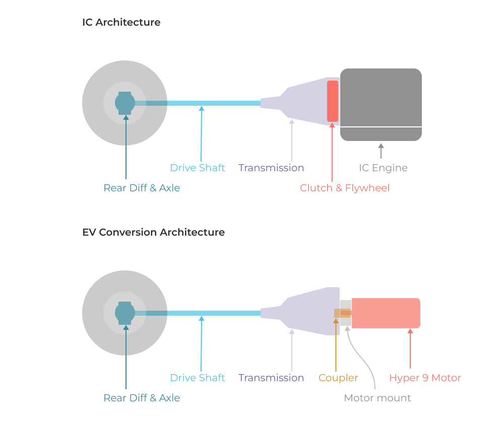
In addition to the modifications to the driveline, we’ll also have to figure out how to secure this entire system structurally, now that we can no longer rely on the combustion engine and it’s chassis mounts to constrain the transmission. We’ve already got our hands full with driveline design and reverse engineering several components that we need to interface with, so the rest of this article will focus on the motor mount and coupler design work needed to adapt the Hyper9 to the transmission bellhousing. We’ll tackle the structural mounting concerns in the next article so stay tuned!
Motor selection, vehicle scanning & mockup
As a quick refresher, Dave used ChatGPT to help him understand the torque and speed requirements needed to adapt an electric motor with the stock gear ratios. The next task for the team was to figure out how to locate all of these components in the vehicle.
Scanning
Given the age of the vehicle and lack of accurate documentation, our plan was to start with a 3D scan of the engine bay to help us move into CAD and make sure what we are designing will actually fit. Since we’re not dealing with a metrology level accuracy problem, we figured hobby or enthusiast grade 3D scanners would be more than capable enough to get us started.
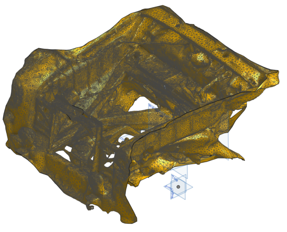
We narrowed down our options to three scanning solutions: the Einstar, the Revopoint, and the Polycam app for phones. Polycam is free so it seemed like a logical/low risk place to start, and we’ve definitely been pleasantly surprised. If you find yourself doing any reverse engineering work or adapting a new design to an existing undocumented system, the Polycam app is a great way to get a general sense of space that you can use for initial component positioning in CAD and rough layout. Our number one learning from this process was the realization that unless you really need high accuracy metrology, free scanning apps are a great solution that don’t require much effort or cost. Our plan is to use other measurement methods combined with 3D prints to test fitment at critical interfaces.
To get a sense of scan quality, take a look at this mesh model Dave generated using Polycam for the first time.
Initial CAD Fitment
Dave brought that mesh into OnShape and added some approximate planes to locate a simplified model of the transmission. We also created a more detailed model of the interface to the transmission bellhousing. This gave us a baseline model to use for initial component design.
Coupler Design Requirements
With the baseline model in hand I could start the coupler design in earnest. Here’s a quick look at the design requirements for adapting the Hyper9 to the existing transmission.
- Hyper9 interface: H6 shaft fit with 1/4” keyway.
AI Design Prompt: https://chat.openai.com/share/4ef62ae0-f107-41cb-9f27-3f333d1279e1 - Transmission interface: Some ancient spline design from the 1950s? Who the hell knows?
- Torque: 163 lb/ft peak torque.
- Assembly: Coupler will be attached to the Hyper9 first and then slip fit to the transmission spline during assembly. It must be easy to remove for service and disassembly.
- Manufacturability: Must be manufacturable via fictiv.com, which gives us a boatload of options but realistically we’re aiming for CNC machining and/or EDM if necessary.
- Mechanical fuse: We had initially considered designing the coupler to function as a ‘mechanical fuse’ in the system. This would involve purposefully designing the coupler in such a way that it fails before the internal transmission components might fail due to overload conditions. In practice we abandoned this idea because the peak torque of the electric motor is so similar to the original combustion engine. Only time will tell if this was a good idea!
Spline Reverse Engineering
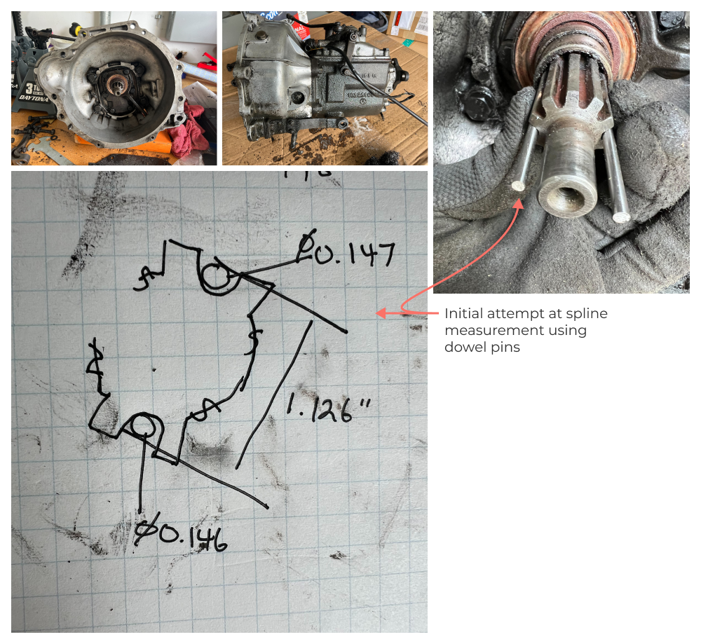
The first tricky problem involves the existing spline interface on the transmission. With limited home shop measuring tools (calipers and a few gage pins) we attempted to reverse engineer the spline geometry. Our initial approach involved measurement of the spline tooth root and crown width (captured in this Five Flute issue). We combined this with a dual dowel pin diameter measurement shown below, to approximate the tooth profile.
Fit Problems!
We used this initial geometry to print a test article with a range of spline profiles (a few thou apart) in order to test fit on the transmission output shaft. Spoiler alert….it didn’t work.
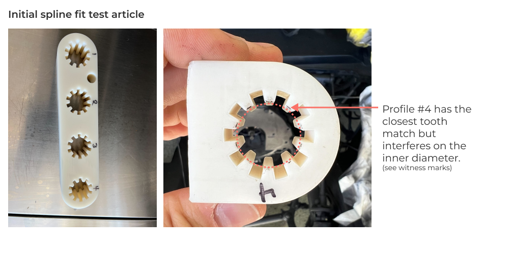
After a few modifications and a reprint, we arrived at a spline geometry that fits, albeit with quite a bit of geometric uncertainty due to print tolerances.
Coupler geometry and analysis
Here’s a Five Flute drawing review that includes a few iterations on the coupler drawing and the team’s markup/comments working through a few issues. Feel free to leave comments or ask questions about the design directly on the drawing yourself (you’ll need a free account).
I took the 3D model from OnShape and imported it directly into a SimScale static FEA environment to analyze behavior under peak torque conditions. Here’s a quick summary of the model setup for all you FEA nerds out there. Note: If you’re an FEA novice, you might want to check out this article as a refresher!
geometry: Since the coupler geometry is fairly straightforward I didn’t do any defeaturing of the model. It’s just a direct import.
material properties: I’m using the stock aluminum properties in SimScale which has a modulus that is likely within a percent or two of Al 6061-t6.
boundary conditions: Since the spline side has so much contact surface area, I constrained that side and applied a load directly to the keyway face on the opposite end. This overconstrains the system and is likely not representative of spline forces, but my expected initial failure point is at the keyway so I still think the model is reasonably accurate.
mesh: I’m using Simscale’s standard TET mesh algorithm which seems to be pretty darn good at adapting local mesh coarseness/fineness based on geometry.
results: Here is a Von Mises stress contour showing failure initiation at the keyway face. Note I’m scaling color gradients so that red starts around 18ksi (below the material failure point).
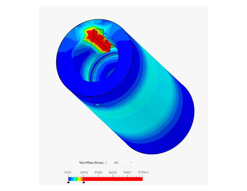
We’re not going for an optimized design here, but more of a sanity check on this approach which we’ve passed with flying colors in my opinion. The safety factor under max loading is a slightly scary 1.2, but we want to use an aluminum coupler for ease of machining and cost, so thats about the best we can do for the keyway design. Plus we’ve accidentally designed a mechanical fuse of sorts that may end up protecting the transmission in the event of an unexpected overload condition!
Motor mount design
With the coupler geometry in hand, the motor mount design is straightforward. It’s simply a matter of matchdrilling holes in the transmission face plate to pick up 4 mounting holes on the Hyper9.
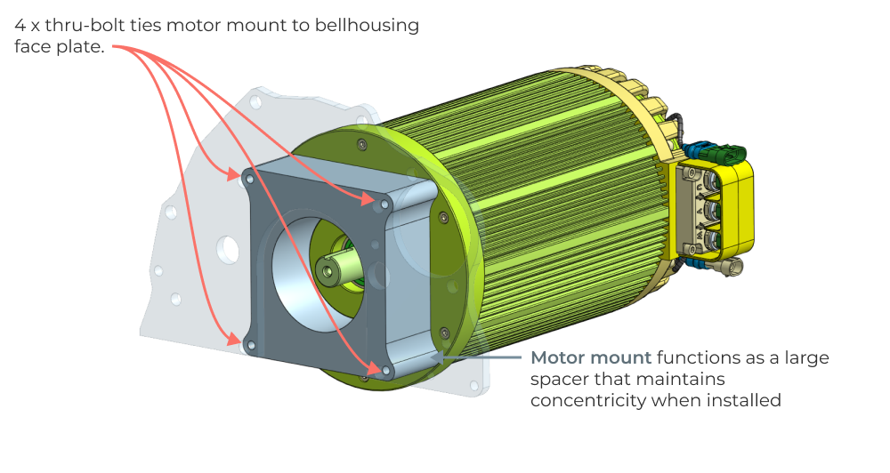
The current plan is to CNC machine this as a monolithic block out of 6061-t6 aluminum.
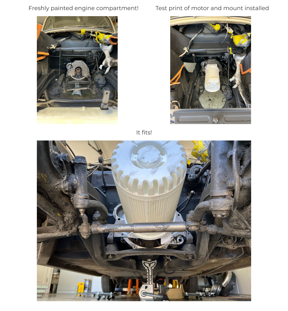
Test Fit
To gut check our scan data, we printed a model of the Hyper9 and motor mount that we could install in the vehicle to verify clearances. The great news is everything fits with room to spare.
Coupler Manufacturing
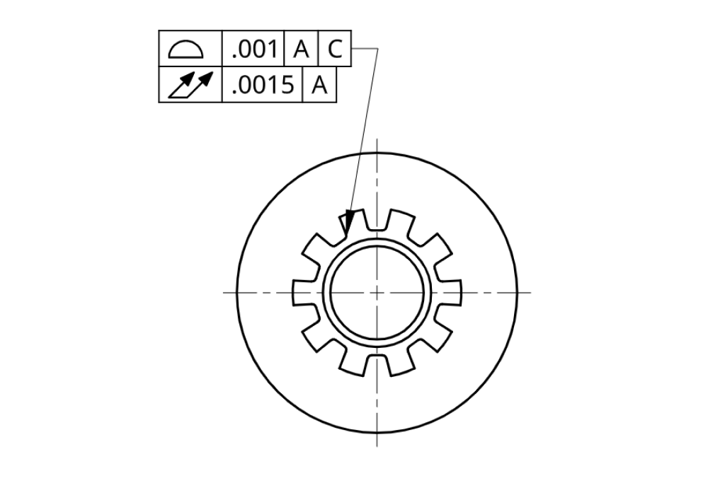
The coupler is a rotationally symmetric part with a keyway on one end and a 10 tooth spline on the other. Here’s the manufacturing drawing that we made for this part to generate quotes with fictiv.
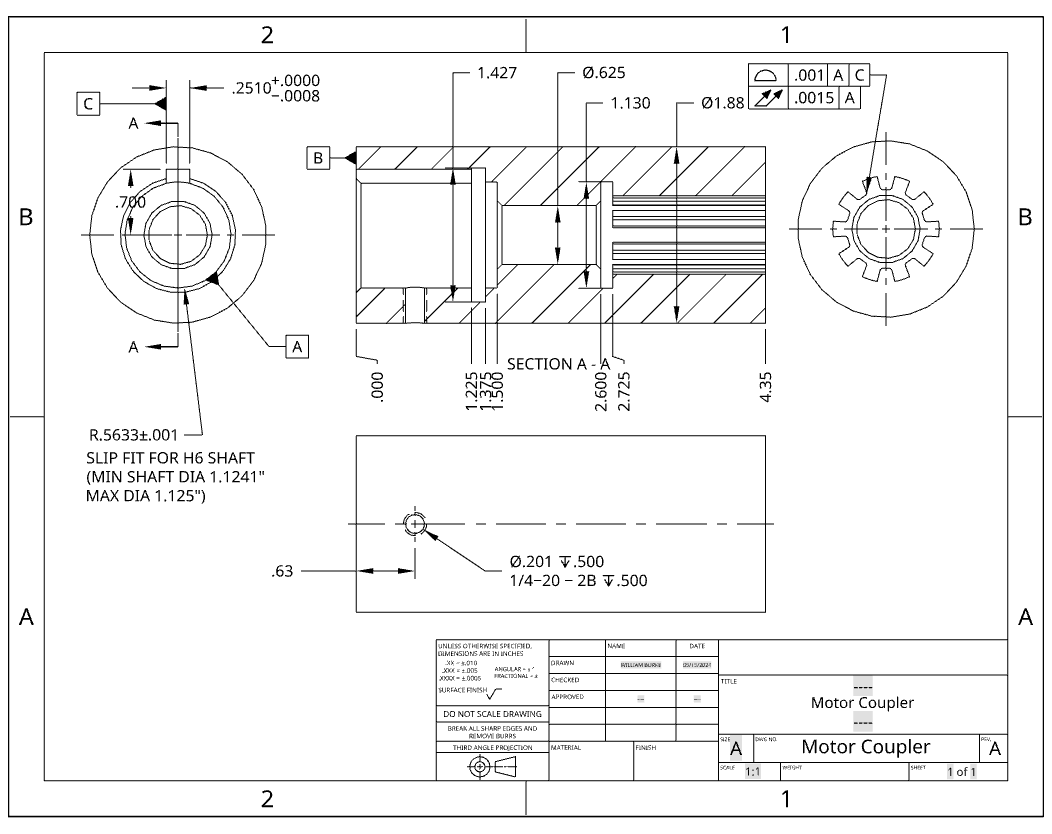
The tricky aspect of this part is the spline and keyway cutting. This left us with two viable options for machining these features, sinker EDM and broaching. My suspicion was broaching in a turret lathe with live tooling would be the cheapest option.
In production a very tight profile tolerance would ensure uniform contact stress at the spline tooth interface. For this project, we’re OK accepting a bit of component wear and treating the coupler as a serviceable component with a relatively short life (this is a Sunday cruiser after all).
Conclusions
After this first team design push we have a motor that fits, mounted to a simple spacer style motor mount, delivering torque through a custom coupler that slip fits on the transmission. And all it took was 5 team meetings on Zoom, a phone scanner app, 4 3D print test articles, a couple late nights after work, and lots of coffee. Who said engineering was easy!? This project is a great reminder that even the simple looking stuff takes effort, collaboration, and iteration to get right.
What’s Next
In the next article, we’ll continue with the drivetrain packaging exercise by tackling the extra transmission mounting now that the IC engine is gone, along with mounts for controllers and other auxiliary hardware.