Intro
Hi enginerds! This is the first in a series of reverse engineering and teardown focused articles that we’ll be doing in 2024. These will not be your typical teardown blog posts. The goal with this series is to do some reverse engineering on popular products that have interesting mechanisms and design constraints that we can learn from. The focus will be on product engineering, design for manufacturability, analysis tools & techniques, and how you (dear readers!) can incorporate any discoveries and lessons learned into your own product development practice.
If you have a product you’d like us to reverse engineer and teardown, send a request to support@fiveflute.com and we’ll add it to our list!
Engineering Teardown
Product overview
The Ryobi Plus One Jigsaw is a consumer grade (i.e. affordable) powertool aimed primarily at the DIY and hobbyist market. From a design perspective I would expect to see many cost saving measures and design compromises in order to reduce the BOM cost between $25 and $75 less than “pro-sumer” and professional contractor grade tools like Makita or Milwaukee. Because of the cost constraints, tools in this category can sometimes take shortcuts in terms of reliability, durability, and materials that lead to wear or premature failure. Let’s dive into the overall architecture and see if we can spot any of the compromises that the Ryobi (owned by Techtronic Industries or TTI) engineers made.
Architecture & teardown
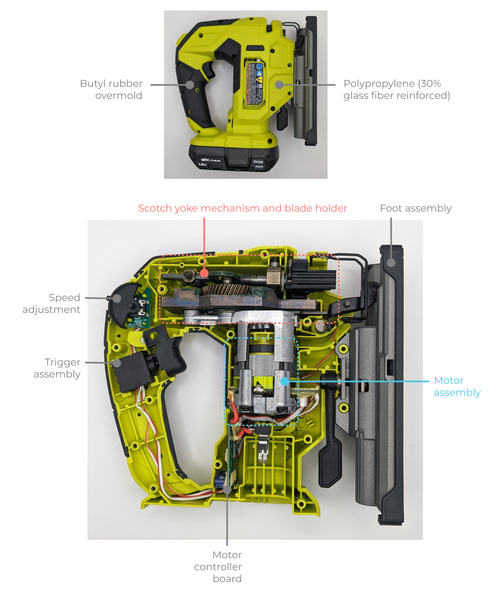
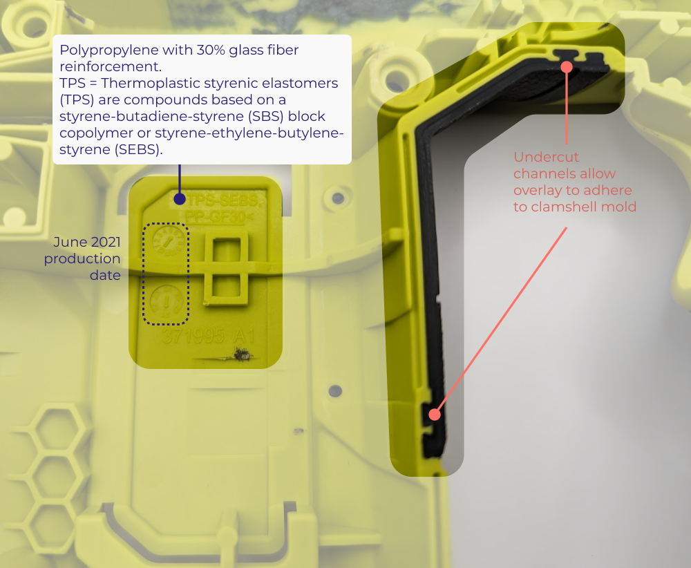
Unsurprisingly, this saw uses the classic hand power tool architecture with a two piece plastic enclosure with butyl rubber overmolding for user affordances (i.e. grips) and industrial aesthetics. The clamshell construction is injection molded polypropylene with 30% glass fiber reinforcement and TPS-SEBS elastomeric overmold.
Mold details and material choice
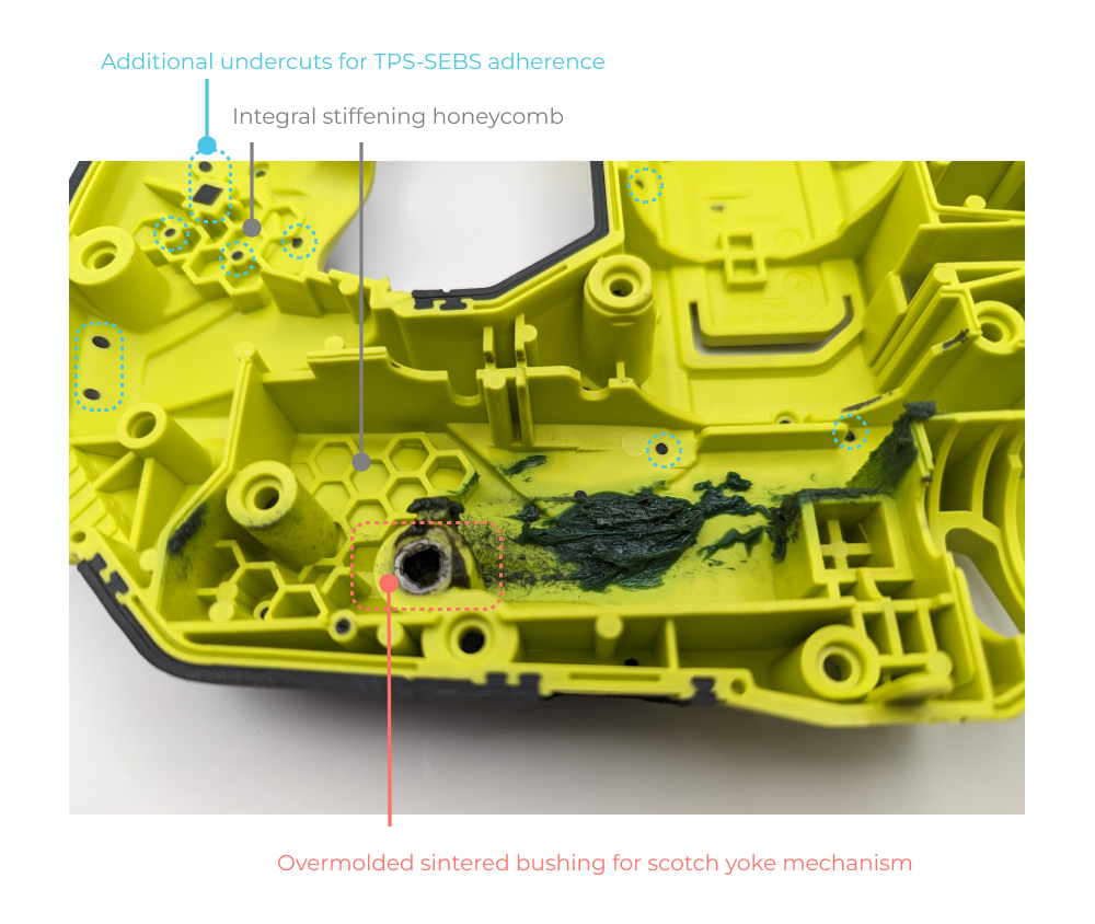
Many power tools use PA6 Nylon with 30% glass fiber reinforcement so I’m a bit surpised to see polypropylene in this tool. My guess is that this is a cost saving measure that would have minimal impact on performance. With the glass fiber reinforcement polypropylene has excellent strength and impact resistance. Here’s an absolutely ancient but informative thread comparing PP and PA6 (nylon) that covers some of the function and manufacturing differences between these materials. Note the undercut geometry of the clamshell that allows the TPS-SEBS overmold to stay connected to the clamshell with positive lock.
Overall the mold quality is quite high for such an affordable tool. I don’t see any die grinding or other “apprentice marks” on the interior surface indicating the part is releasing from the mold properly. There are no visible knit/weld lines and despite the wide range of wall thickness, boss and rib size, there is no obvious warpage or sinkage.
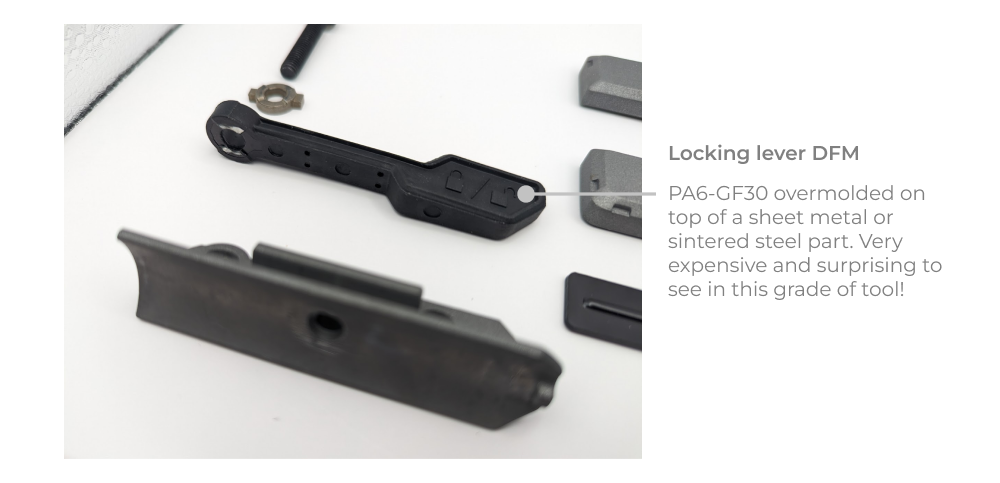
Foot assembly
Looking at the adjustable foot assembly, there are a variety of different manufacturing processes used at the part level. The die cast components are made from A380 Dynacast, which is a great choice given it’s balance of mechanical and thermal properties combined with excellent dimensional stability. There are a number of sintered steel components in the adjustment mechanism for the foot angle, along with some 30% glass fiber reinforced nylon plastic parts.
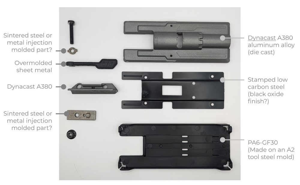
Perhaps the most surprising part (from a cost perspective at least) is the overmolded foot locking lever. It appears to be either low carbon steel sheet metal, or a sintered steel component with a nylon (PA6) overmold with glass fiber reinforcement. I would have expected this to be a pure plastic part on a hobbyist grade tool.
Scotch yoke and motor assembly
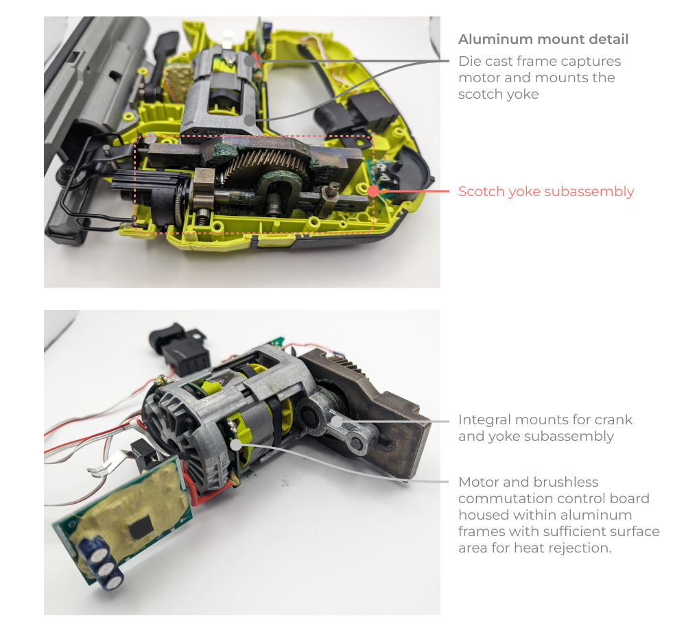
The saw uses a scotch yoke mechanism to convert the rotary motion of the brushless electric motor to the reciprocal linear motion of the saw blade. The entire mechanism is compact and quite elegant. It uses a pair of die cast aluminum components to capture the motor and mount the scotch yoke assembly. The motor frame mounts guides for positioning and constraining the yoke, as well as locating the crank gear relative to the drive gear (7:46 gear reduction). From an assembly standpoint it allows the entire mechanism and motor to be installed as a single unit from one direction, which is great design for assembly!
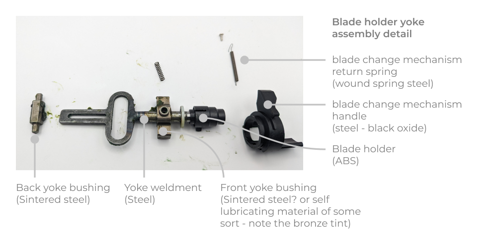
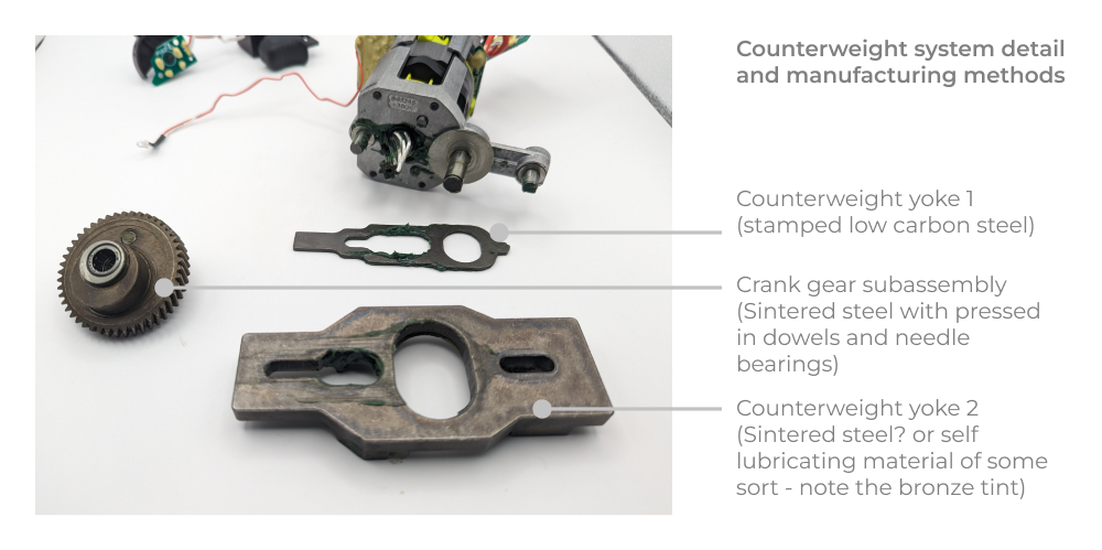
The primary yoke (blade holder subassembly) consists of a shaft weldment in sintered guide bushings. The blade holder itself appears to be a machined steel component (in black oxide finish?) pressed onto the yoke weldment.
Further disassembly of the scotch yoke assembly reveals that there are in fact two additional scotch yokes and two eccentric lobe cranks on the motor side of the main crank as well. Two of these lobes are 180° out of phase with the primary crank bearing (that drives the saw blade). My best guess is they are counterweights in order to help balance out the vibration induced by the saw blade motion.
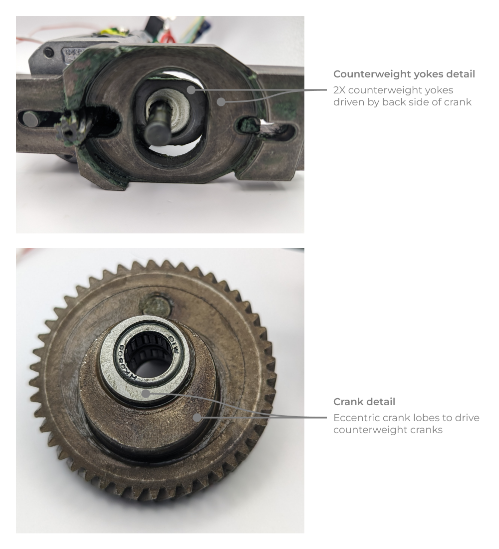
Because the stroke length of the counterweight yokes is shorter, the mass of the yokes is larger than the blade holder shaft in order to balance the system. Overall this mechanism is very tightly packaged and nicely implemented. Lets take a look at the component manufacturing methods in this subassembly.
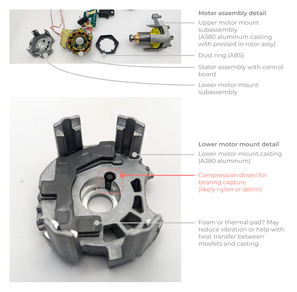
With the cranks removed, disassembly of the motor is possible. I found a neat cost saving design trick in the lower motor mount casting. The designers opted to use a plastic dowel insert in order to retain the lower motor bearing. This relaxes the machining tolerances on the cast lower motor mount and makes bearing installation easier and more consistent. Here’s a breakdown of the assembly that also highlights this design trick.
Mechanism Analysis - the importance of counterweights
We can get a sense for the importance of the counterweight system by analyzing the inertial forces associated with the back and forth mechanism of the blade holder. Using the Five Flute scotch yoke design worksheet (excel download) I calculated the peak acceleration of the yoke. I couldn’t find specs for the motor so I ballparked the peak RPM at 5000. The gear ratio of the mechanism is 46:7, so the RPM at the crank is 760 (79 radians per second). This yields a peak acceleration of 3174 inches per second squared (80.6 m/s^2). The mass of the blade holder (yoke) and blade is approximately 0.075kg. Using good ol’ Newton’s second law (F = ma) we can compute a peak inertial force of 6.045 Newtons (or 1.36 lbf). This might not sound like a lot, but when you consider the rotation speed and the sign change, this would lead to a difficult to control vibration felt through the saw user’s hand. With this in mind, it becomes clear that an effective counterweight system is essential to the user experience.

Additional Design Tips
I wanted to highlight a few additional thoughts on the design that you can learn from and apply to your projects.
-
When dealing with high rotational velocity systems, you need to consider dynamics (not just kinematics) of the system. Bearing wear, user experience, and fatigue life of components will be driven in part by inertial forces as angular velocity increases.
-
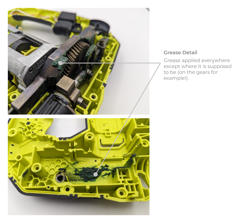
This saw has some pretty standard looking grease, hastily applied I might add. When dealing with systems that don’t get serviced regulargly, consider lubrication more thoughtfully. In this case I would recomend using a grease with molybdenum disulfide particle in it, because they will embed in the gear teeth faces and provide longer lasting wear protection and friction reduction. Additionally, I would make sure the grease is actually applied to the wear faces correctly (there is none on the gears!).
-
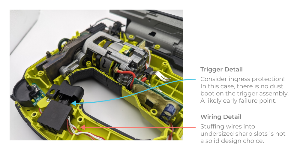
On high vibration devices, wire routing should not be an afterthought! In this saw, the trigger wiring was wedged into the clamshell and pinched in several locations. I even saw the insulation worn away down to bare wire because of damage on installation. With vibration added on top of this, failure is likely.
-
At some level ingress protection should be considered for most designs, especially for a tool that will be used in a dusty and dirty environment! In this case the most glaring design issue I see is the lack of a dust boot in the off-the-shelf trigger assembly. This will likely fill up with abrasive saw dust and fail significantly earlier than the other mechanism components.
-
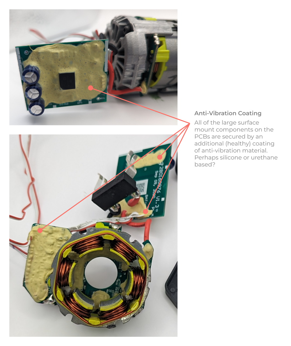
One detail I really like is the consideration of the effects of vibration on the printed circuit board reliability. All of the PCBs have an elastomeric like coating to secure the surface mount components. This is an effective way to mitigate fatigue damage to solder joints caused by high frequency vibration and shock.
Closing Thoughts
Overall I was quite impressed with the Ryobi Jigsaw. I expected to see a much more cobbled together design. There are some worrying design decisions that may impact overall reliability (grease placement, wiring wear and switch component choice), but in general it appears mechanically sound. The components in the scotch yoke mechanism are well thought out, but the material choice and finish is a bit crusty for lack of a better word. The mold quality is incredible all things considered, and seems on par with higher end tools like Milwaukee and Makita. What you can’t glean from a simple teardown however is how much consideration was put into thermal management. Hobby grade tools may not be sized to deal with the duty cycle requirements of professional grade usage. Still, I was quite impressed with how compact the mechanical design was, the robustness of the material choices, and general simplicity of assembly. Hopefully you learned a few mechanical design tips and tricks that you can apply on your projects.
What should we tear down next? Feel free to write us at support@fiveflute.com and let us know. Thanks for reading!
Related
Scotch Yoke Design Worksheet (Excel Download)