Sheet metal design skills are a crucial tool in any engineer’s toolbox, but given how little attention sheet metal design gets in academia, most skills are learned on the job. From consumer electronics, to medical devices, and obviously automotive - sheet metal part design plays a role in most modern products. Because of this, mechanical engineers should be equipped with a first principles understanding of sheet metal design for manufacturability (DFM). In this article, we’ll be taking a deep dive into sheet metal DFM. Starting with the 2D cutting process needed to make a blank, then exploring forming operations necessary for various sheet metal features, and finally concluding with finishing and assembly considerations as well as how to ensure your team puts out good designs that your manufacturers can understand and make at a high quality.
Blank preparation - 2D cutting processes
There are a variety of suitable cutting processes for sheet metal, but we’ll be focusing on the most common processes used to prepare sheet metal blanks for bending: waterjet, laser cutting, and punch pressing.
Waterjet
The waterjet is perhaps the most versatile prototyping tool because of its ability to cut a wide variety of materials in an enormous range of thicknesses. From a sheet metal perspective, its important to understand how waterjet cutting can impact the finished formed part. The main consideration with waterjet cutting is the cut quality and kerf width.
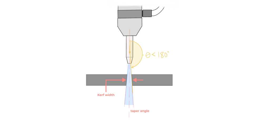
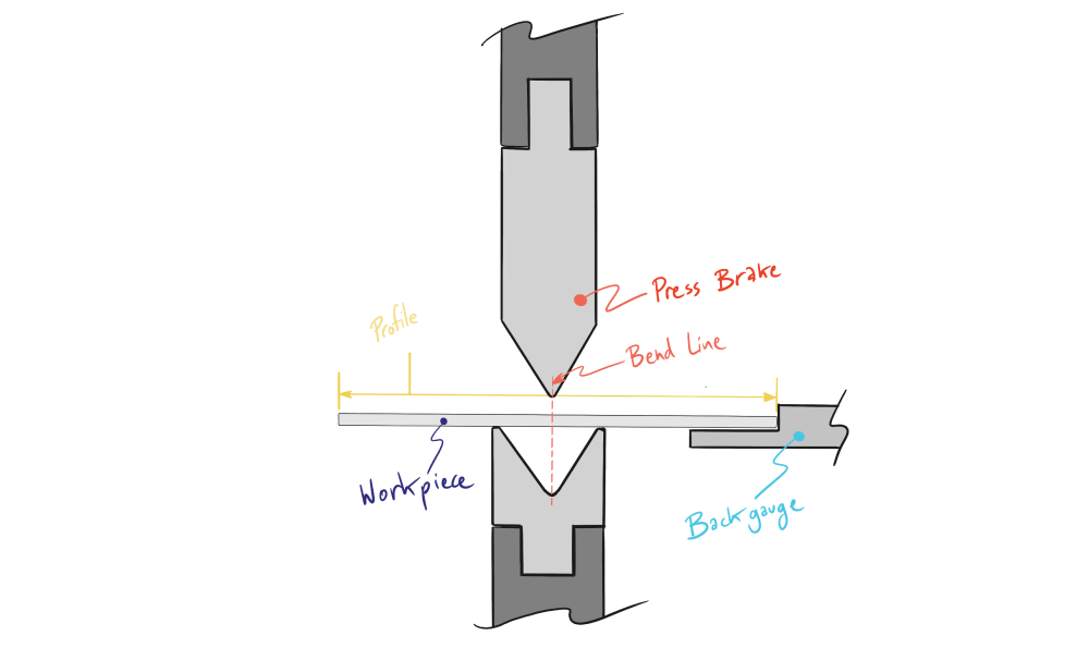
Waterjet machines can have widely varying tolerance capabilities, from ±0.002” to ±0.020” depending on nozzle health and machine upkeep. Additionally, edge quality can suffer at locations where the jet has to pierce through material (small holes or slots) or at areas of abrupt directional change like sharp internal corners and acute profiles. Be sure to consider the profile tolerances needed to locate your bends accurately (most bends are located relative to a backgauge set against the edge of the workpiece).
Laser cutting
Laser cutting is typically more suitable for medium production volume compared with waterjet. Tolerances are often superior to waterjet, but lasers do leave a heat affected zone and work hardening proximal to the cut. Laser cutting also has an associated kerf that must be considered, but generally this kerf width is on the order of 0.75 - 1.0mm (0.030” - 0.040”). Note that laser cutting is not just for steel components as modern fiber lasers with high power are capable of cutting aluminum, copper and brass, despite their high reflectivity and heat conductance.
Punch press
The punch press (CNC turret punch) is the most economical solution for high volume sheet metal part production. Low volume production design should consider what tools and associated geometries are standard (holes, slots, etc…), while high production volume justifies the creation of custom tooling for part specific geometry.
Punch presses use a punch and die in combination to provide a controlled shearing action of the sheet. The edge quality, burrs, and deformation of the sheet are driven by the relative tolerances of the punch and die combination. To better understand the mechanics of the shear cut action, we can take a look at a typical punch and die setup.
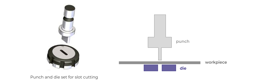
For punched parts in particular, tolerances should be maximized in order to reduce cost. Tigher tolerances require closer fits between the punch tool and die, which in turn causes greater wear during normal operation.
Material orientation
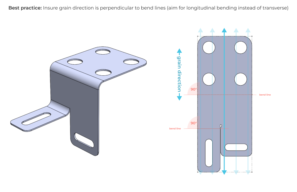
When cutting blanks before forming, designers should consider how parts will nest on a large sheet, and how the grain or roll forming direction of the material aligns with the planned bends. Parts that nest efficiently can save material cost by reducing scrap cutoff volume. Constraining this efficiency however is the need to consider the material grain direction relative to formed features. Depending on the exact material, it can sometimes be required to align the grain direction as close to perpedicular with bend lines as possible. Failure to do so can result in cracking and weakness at bends, especially with heat treated or less ductile metals like 6061-t6.
Forming
After a blank is cut, it must be formed consistently into the final sheet metal component. There are many kinds of forming operations, but this article will focus on the most common press break and stamping operations. From a first principles perspective, sheet metal design for manufacturability is based entirely on the design engineer’s understanding of how desired features and feature tolerances are impacted by the range of anticipated forming operations. In this section we’ll review theese forming and cutting operations and establish DFM guidelines and best practices that you can apply to most parts.
Bends and bend allowance
A basic (single axis) bend is the most foundational sheet metal forming operation. Despite the relative simplicity of the bending process, there is a lot to consider as a designer. Principally, both design engineers and manufacturers should understand how sheet materials will respond to the stress of forming operations. With a basic bend this material response is characterized by a bend allowance. Bend allowance describes the length (typically arc length) of the neutral axis of the material in the bend area. Bend deduction describes the amount of material stretch at the outer radius needed to create the bend.
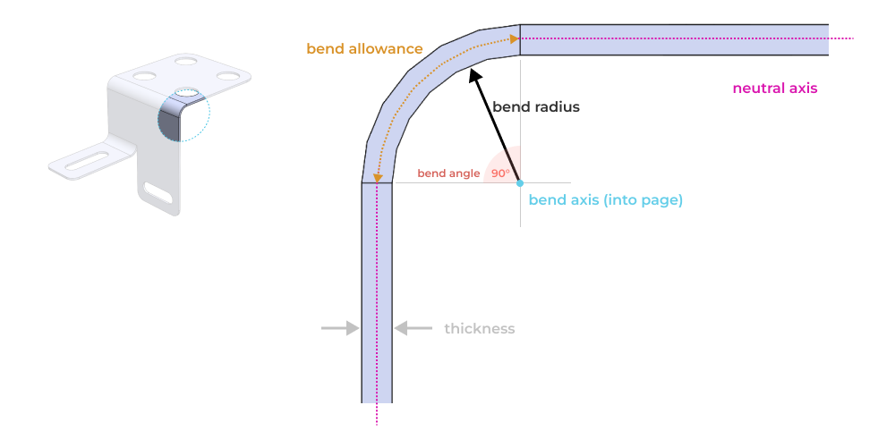
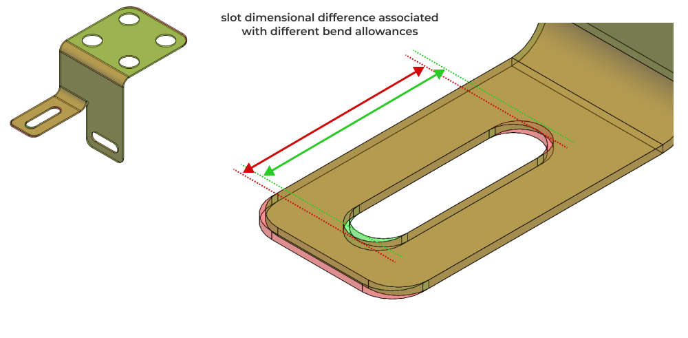
Understanding the bend allowance allows designers and manufacturers to accurately relate the 2D geometry of the blank to the finished 3D geometry (as bent). Improper bend allowances can cause tolerance issues for features located across one or more bends.
Bend allowance is a function of material and tooling, so be sure to speak with your manufacturer about their capabilities during design.
Minimum bend radius
By definition, bending operations cause material yield and permanent deformation. But how much stress is allowable during forming operations without compromising part functionality?
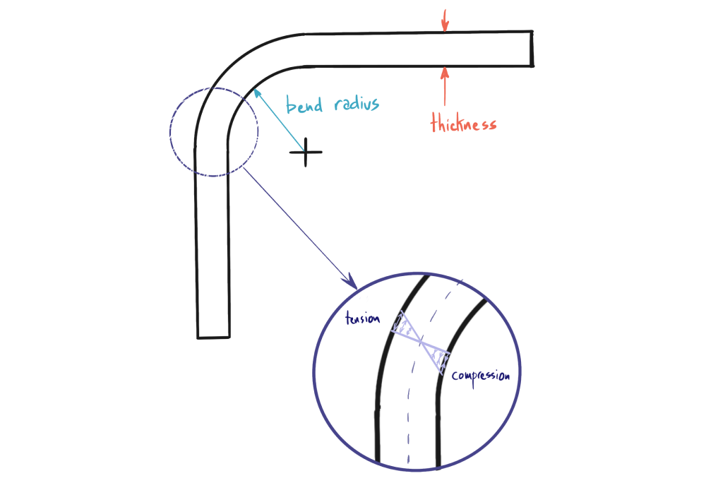
The simple answer to this question is for designers to think of bend radii in terms of ratios relative to the part thickness. For easy to form and highly ductile materials, it’s best to keep the bend radius greater than or equal to the material thickness. For less ductile, harder materials, you will need to increase this up to several multiples of material thickness. Aluminum 6061 in a T6 hardened state for example, will perform well with a minimum bend radius of 4 x thickness or greater. One difficult aspect of sheet metal DFM is that there is no set answer to the minimum bend radius design question. Different materials, material thicknesses, plate and sheet forming techniques (hot rolled vs cold rolled), and different equipment will all impact how stress and deformation is induced in the formed part. First articles and a good quality inspection plan are especially important for sheet metal parts. That said, here are some conservative initial guidelines for minimum bend radii in different materials.

For more on the topic, check out this article from the Fabricator.
Bend relief and material tearing
Some designs require bends to be located immediately adjectent to unbent material. In order to prevent crack propogation and material tearing, its best to design in some bend relief. Bend relief is the removal of a small portion of material at the edge of a bend where the curved part of the bend meets the flat unbent material. This allows for controlled deformation of the bend and prevent stress concentration at the bend interface. Here’s a quick comparison of a design with and without bend relief.
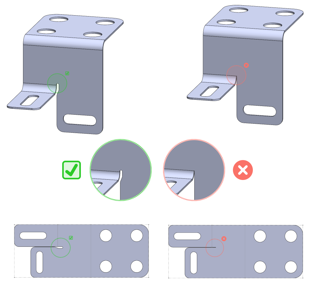
Note: it’s a good idea to aim for a bend relief with a width greater than or equal to half material thickness.
Holes
When using turret punching to make 2D blanks, there are some key considerations regarding holes. The first is to consider your specified hole size relative to the thickness of the material. Avoid very small holes (diameter less than material thickness), as they might not punch cleanly. Additionally, holes should be located approximately 1.5 times material thickness away from edges and 2 times material thickness apart from eachother in order to avoid material distortion.
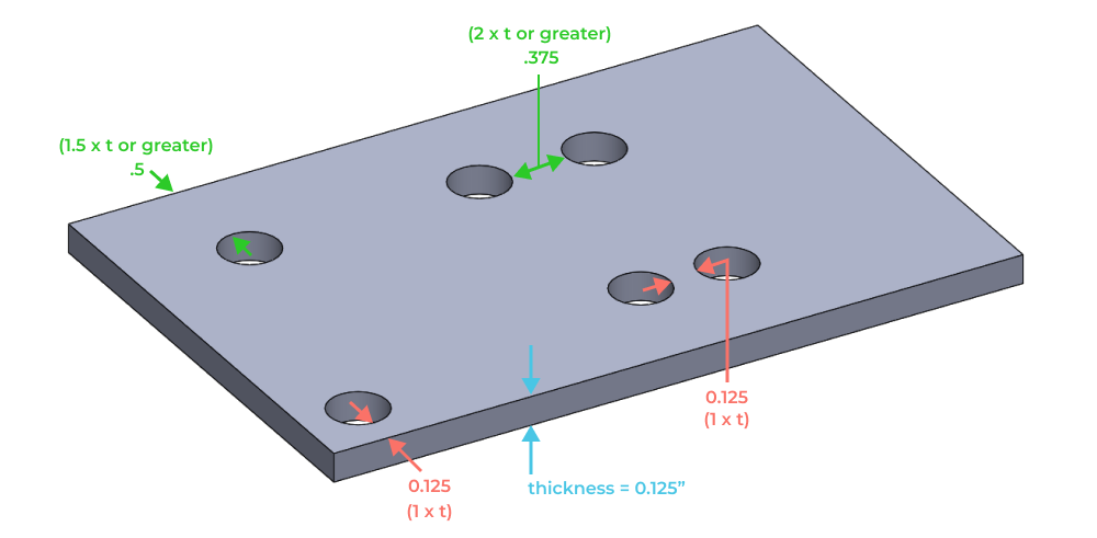
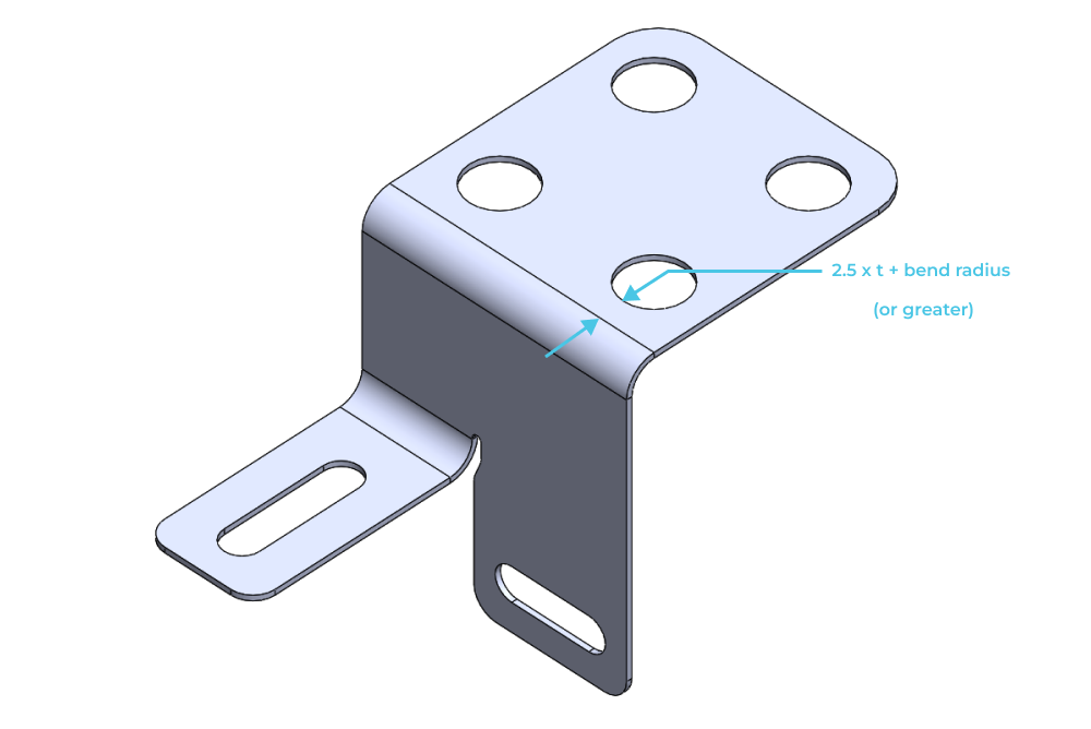
In order to avoid distorting holes near bends, place them 2.5 times thickness plus one bend radiius away from bends.
Note: if you are designing in through-features that require more material deformation to form properly, such as louvers or extruded holes, you will need to increase the distance relative to bends and edges in order to prevent malformed features and sheet deformation.
Slots, notches and tabs
Slots notches and tabs follow comparable guidance to holes, summarized below:
- Slots should be wider than the material thickness.
- Because of larger material removal, slots should be positioned 2 times material thickness away from material edges and 4 times thickness away from bends.
- Ensure notches have a minimum width of the material thickness.
- Tabs should be at least 2 times the material thickness in width.
Stiffeners
There are a variety of techniques that can be used for stiffening thin sheet structures. In general these techniques all involve changing the section modulus of the material to better resist anticipated bending loads.
Beads
You can use beads for preventing drumhead vibration and to add bending and torsional stiffness to rectangular sheet bodies and panels.
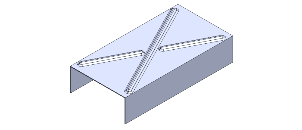
Beads can be rolled into the face with a bead roller, or created as a drawn feature on a press.

From a DFM perspective you should anticipate material thinning at the bead location that increases as a function of bead depth. Guidelines are not useful in these cases as the material response is geometry specific (often requiring FEA to model correctly).
Coining and Embossing
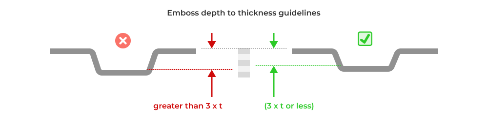
Coining and embossing allow designers to create raised or relief features by cold working the metal through the application of extremely large forces between the punch and the die. Embosses are created by stretching and thinning the flat sheet material. To prevent tearing or fracture, the maximum depth of embossed features should be less than or equal to three times the material thickness.
Corner Ribs
To add bending stiffness to a bend, ribs can be created by pressing a v-notched tool perpendicular to the bend axis. This technique is commonly seen on construction brackets.
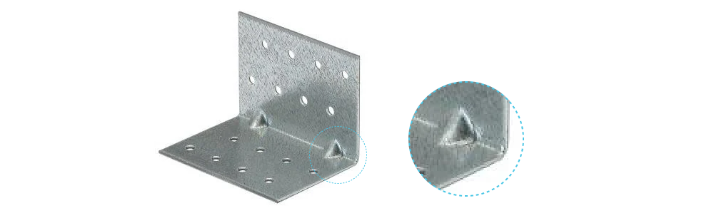
The exact geometry of ribs and material response is tooling dependant, so consult with your manufacturer during the design process.
Hems
Sheet metal hems are features where the edge of a sheet metal part is folded back onto itself. In addition to increasing material stiffness locally, they are used for safety, aesthetics, and to join sheet bodies together. There are a number of different hem styles, summarized below.
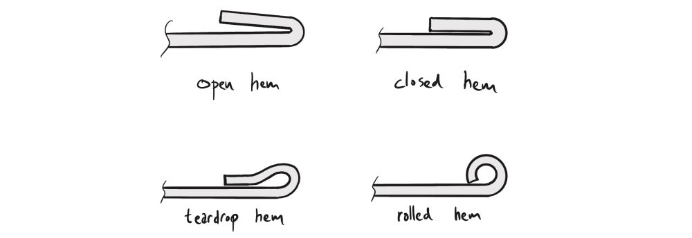
Creating a hem in sheet metal requires special tooling and machinery, often involving press brakes or other sheet metal forming equipment. Proper design and execution of hems is essential to ensure they don't split or deform during the bending process. In general, the same guidance with respect to bends applies to hems as well. Open and closed hems do not work well on hard and brittle materials, instead opt for larger radii afforded by rolled and teardrop designs.
Finishing and assembly considerations
For parts that have a coating (powdercoat, anodize or alodine for example), be sure to consider the dimensional change from the coating. Additionally, consider how parts will be held during the coating process. Often this means a portion of the part will be uncoated. Consider where you want this section of the part to be located and communicate accordingly on your drawings.
As with all manufacturing processes, good DFM at the part level considers assembly simplicity. Where possible, design parts to be self locating, minimizing the need for jigs and fixtures during assembly. With sheet metal in particular, using PEM inserts or rivets instead of welding can save signficant time and money if functionality permits.
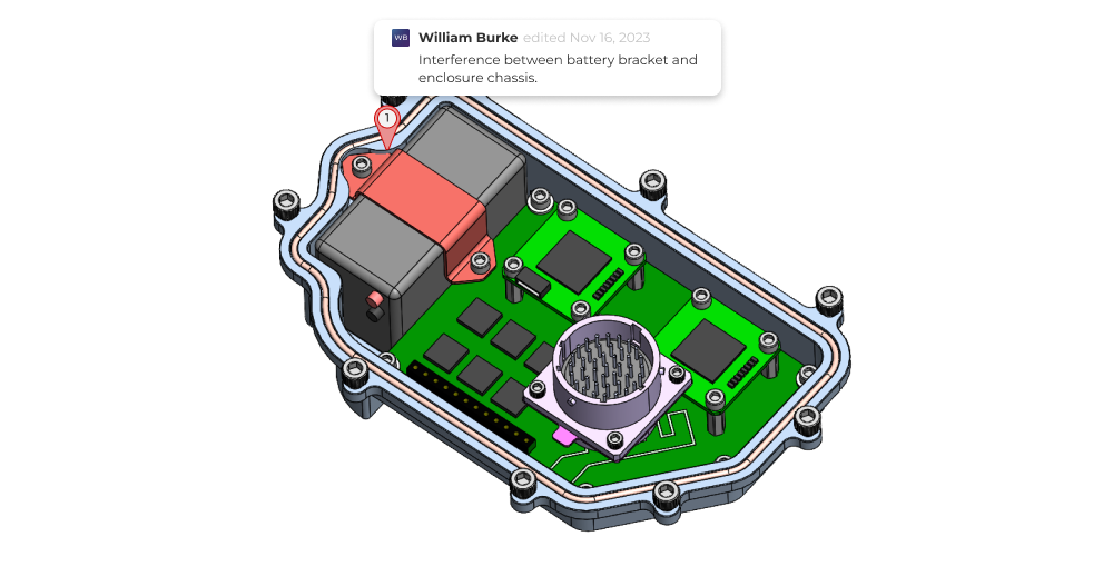
Sheet metal design reviews and drawing preparation
As with any design, mistakes are inevitable. At Five Flute we’re big fans of what we call a continuous design review process. Basically this means running lots of small design reviews so that issues are discovered early before designs develop inertia from integration, and are more costly to correct.
For your sheet metal DFM reviews make sure you check all of the features of your parts against the guidelines in this article. Also be sure to set up your review for success by preparing properly and executing a good review. We’re building Five Flute to help power your continuous design review process. Its the easiest way to share, review and improve your designs. To see it in action, sign up for a quick demo.
For your drawing preparation, check out this article with our top tips for creating better sheet metal drawings as well as best practices for drawing reviews, so you can catch any last minute mistakes before your parts are released. All of your sheet metal DFM work will be wasted if you can’t communicate the requirements of your parts to manufacturers efficiently.
Thanks for reading and good luck with your next hardware project!