(A bit of housekeeping! Since you care about engineering drawings you might be interested in how [Five Flute powers collaborative drawing reviews](/. Take a look, we’d love to help you if we can. Now on to the nerdy stuff! Cheers!)
Introduction
Despite the sophistication of 3D CAD tools, 2D engineering drawings are here to stay. As an engineer designing parts, you will sometimes be responsible for creating and/or reviewing individual part drawings. In this article we will cover the basics of creating high quality engineering drawings for individual part designs so that you can communicate your design and manufacturing intent clearly, as well as review other drawings effectively.
We’ll break down this process into two key focus areas:
-
Anatomy of an engineering drawing - What are the basic components of every engineering drawing?
- The purpose of engineering drawings
- Components of the drawing sheet
- Views and their purposes
- Symbols and lines
- Dimensions and tolerances and inspection
- GD&T
- Drawing notes
-
Key principles for making great drawings - What are the basic “rules” to follow when creating drawings?
- Convey design intent directly
- Build reusable drawing infrastructure
- Pages and views are free - use them!
Anatomy of engineering drawings
The purpose of engineering drawings at the part level, is to communicate to manufacturers what the final part must look like. In that way, a drawing is actually a specification that serves as a contract like agreement between a design organization and a manufacturing organization. Good drawings specify geometry in such a way that the design intent of the part is communicated clearly and preserved despite the natural variability of all manufacturing processes used to create it. The core challenge is to communicate this design intent in as concise and accurate manner as possible. The rest of this article will be focused on this type of communication.
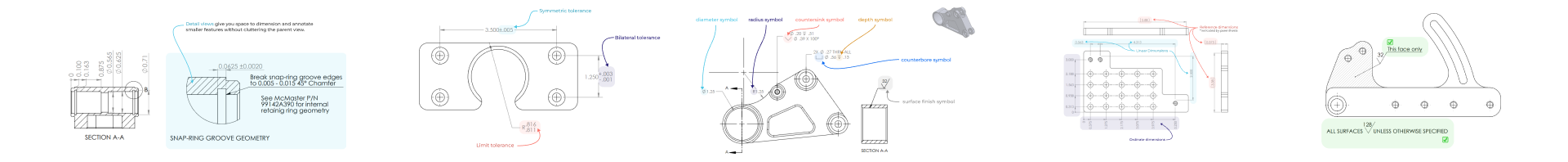
Components of the drawing sheet
Before you can add views and start dimensioning, you need a sheet to draw on. Ideally your company has a library of templates that establish everything you want on your drawing sheet. A basic drawing sheet has a few key elements shown below.
The title block captures critical information about the part, personnel, company and manufacturing process. Title blocks commonly include:
-
Drawing title
-
Drawing number and/or part number
-
Company information
-
Part information
- Material
- Estimated part weight
- Finishing information
-
Drawing interpretation information such as:
- Measurement units of the drawing (for example, inches, millimeters)
- Default tolerances for dimension callouts where no tolerance is specified
- Relevant drawing standards such as ASME Y14.5
-
Personnel information such as:
- Created by (drafter)
- Checked by
- Approved by
-
Boilerplate callouts and general specifications
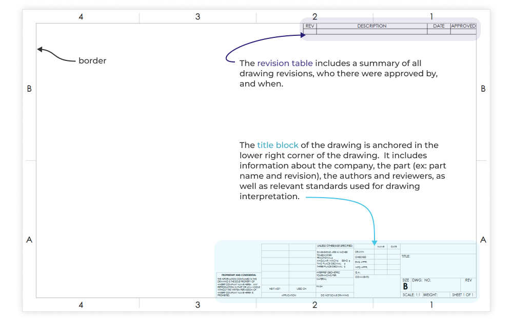
Drawing views and their purposes
Drawing views work together to fulfill one job, communicating 3D geometry in two dimensions. In general, you should include enough views on your drawings to allow anyone to clearly understand the 3D part geometry. Even if you are sending manufacturers both a 2D drawing and a 3D file, it is a best practice to treat the drawing as a stand alone document from a legibility and views standpoint.
Basic views
Typically you should include a main view (often the front view of the part) with one or more orthographic projected views, and an isometric (dimetric or trimetric are also acceptable depending on part geometry). This is demonstrated below on a simple machined component.
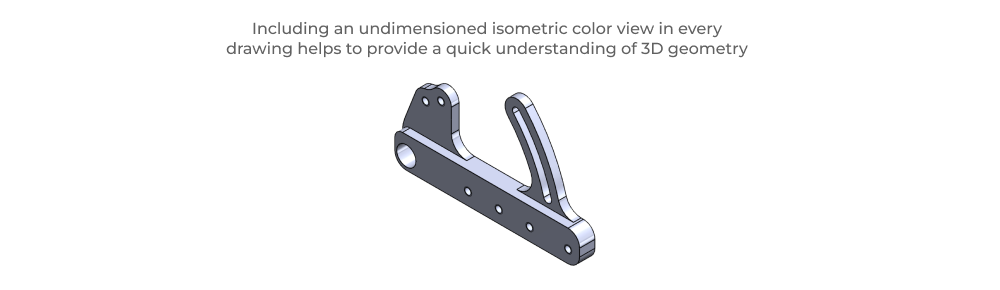
Note: Orthographic views follow a projection standard (1st angle or 3rd angle) which is called out on the title block of the drawing so that everyone knows how to interpret it correctly. Check out this wiki page on projected views to get a handle on both projection standards. Also, it is generally best practice to leave isometric views undimensioned, providing 3D geometry at a glance. Dimensioning should be reserved for in-plane (orthographic & projected) views.
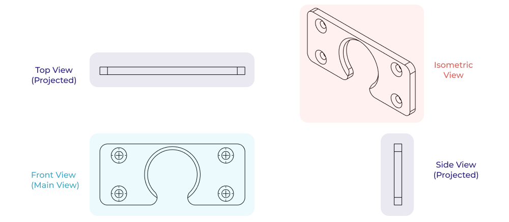
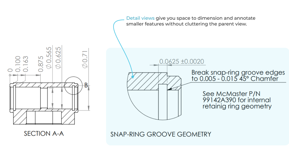
Section views
You may elect to include additional projected views and section views to show geometry which is not included in other views. A section view is a projected slice of the part that provides the part’s projection at a section view plane. The plane is shown on the parent view as a dashed line with directional arrows indicating projection direction. This is perfect for complex hole geometry like stacked precision bores with snap ring grooves.
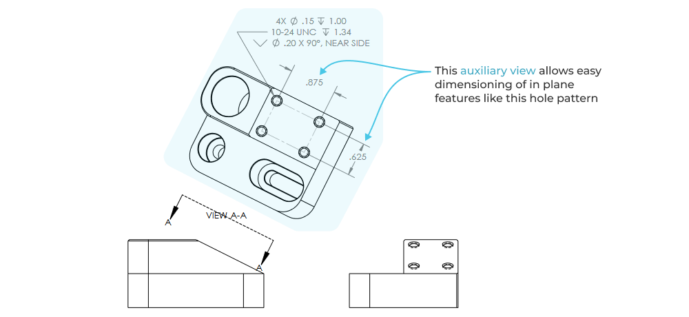
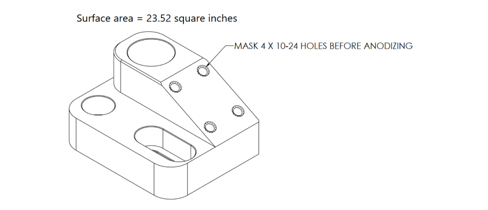
Auxiliary views
Auxiliary views are projected views used to communicate a specific feature set or geometry that is hard to discern from the basic orthographic views. Take the hole pattern on the angled face of part shown below as an example.

The auxiliary view shows the geometry of the hole pattern perpendicular to the face in which the holes are drilled, clarifying hole layout and inspection relative to a new plane that isn’t parallel with any of the three Cartesian (orthographic) planes (X-Y, Y-Z, X-Z).
Detail views
Detail views apply local scaling of features to allow better feature and dimension legibility. O-ring and snap-ring grooves are a common machined feature that benefits from a combination of a section view and detail view to clearly communicate geometry.
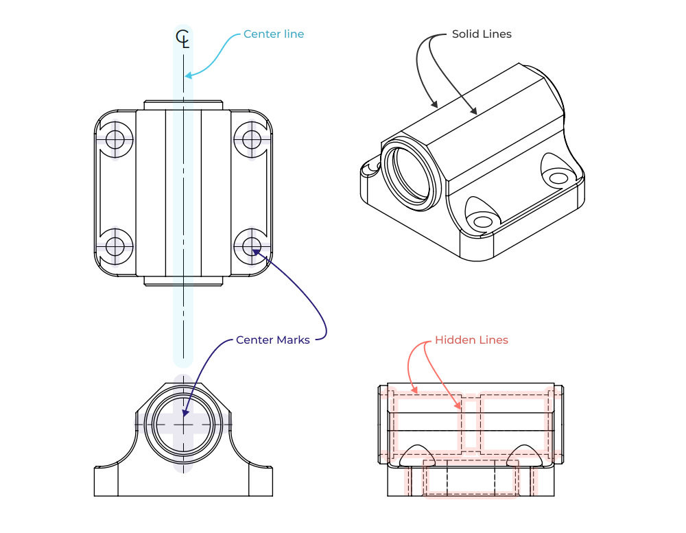
Line types
Modern CAD tools automate much of the line-work, but it helps to have a basic understanding of the various line types used across drawing views.
Continuous solid lines are used to communicate the outer edges and surfaces of parts.
Hidden lines communicate features that are obscured by other geometry.
Center-lines communicate a mid-line between features or line of symmetry associated with a single feature.
Center marks show the center point of holes and other cylindrical features.
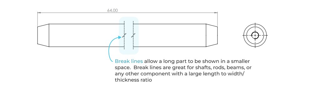
Break lines show when a view has been broken, effectively shortening the key features for legibility. Break lines are used to allow concise dimensioning of long features in less drawing space. Importantly, break lines enable the usage of smaller drawing sheet sizes for long and high aspect ratio parts, improving legibility across the entire drawing.
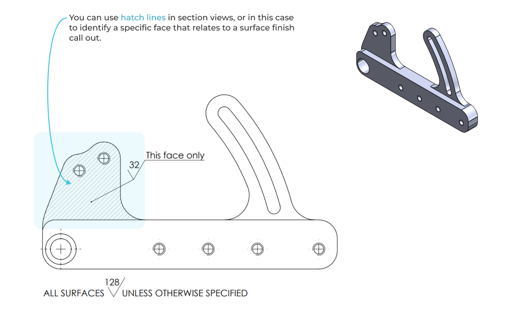
Hatch lines typically indicate the cut faces in a section view. They can also be used to indicate any particular area on a face where an additional specification must be applied.
Dimensions & tolerances
At a minimum, engineering drawings should include dimension callouts on critical features with associated tolerances. These dimensions tell manufacturers what features to measure during inspection, and what the desired limits should be for each feature. Most drawings are dimensioned with a combination of the following dimension types.
Linear
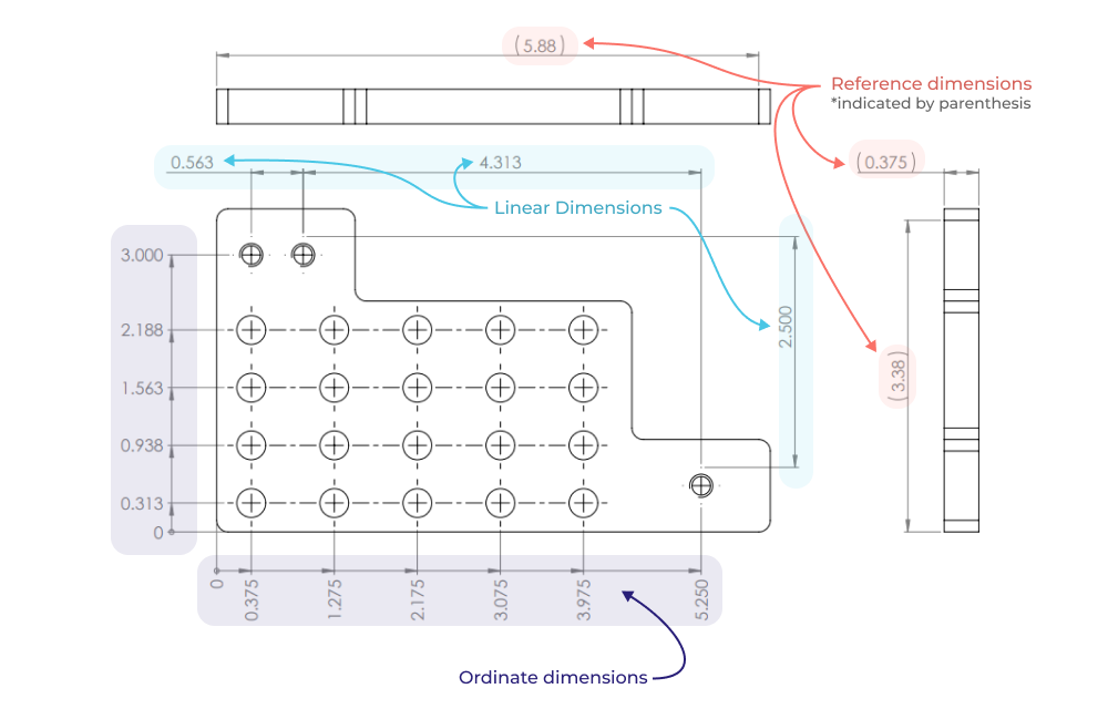
Linear dimensioning establishes a distance between two features, with the dimension being displayed between two extension lines extending from a part view. Linear dimensions are a great way to explicitly establish a critical dimension and tolerance between two specific features. Excessive use of linear dimensions can get messy if extension lines and arrows overlap or crowd each other.
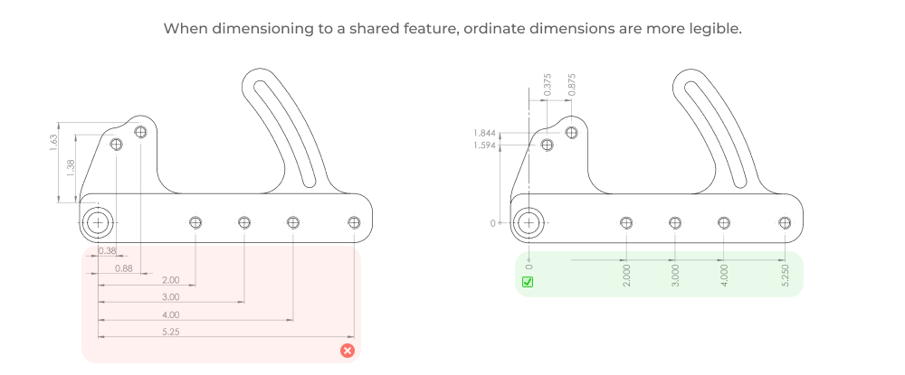
Ordinate
Ordinate dimensioning establishes a distance between a zero (reference feature) and multiple features, with the dimension displayed parallel to, and at the end of, feature specific extension lines. Ordinate dimensions are great for establishing the position of groups of features (ex: hole patterns) relative to a global reference feature.
Reference
Reference dimensions are used to provide information only, and not as a means of specifying important (or measurable) geometry. They are typically indicated using a parenthesis around the dimension value. One of the most common usages of reference dimensions on part drawings is to call out the total part size (bounding box) via reference dimensions on the largest dimension in each orthographic view. This allows machinists, for example, to quickly assess what stock material size will be needed to make the part.
These three dimension types are shown below across the three primary drawing views.
Tolerance types
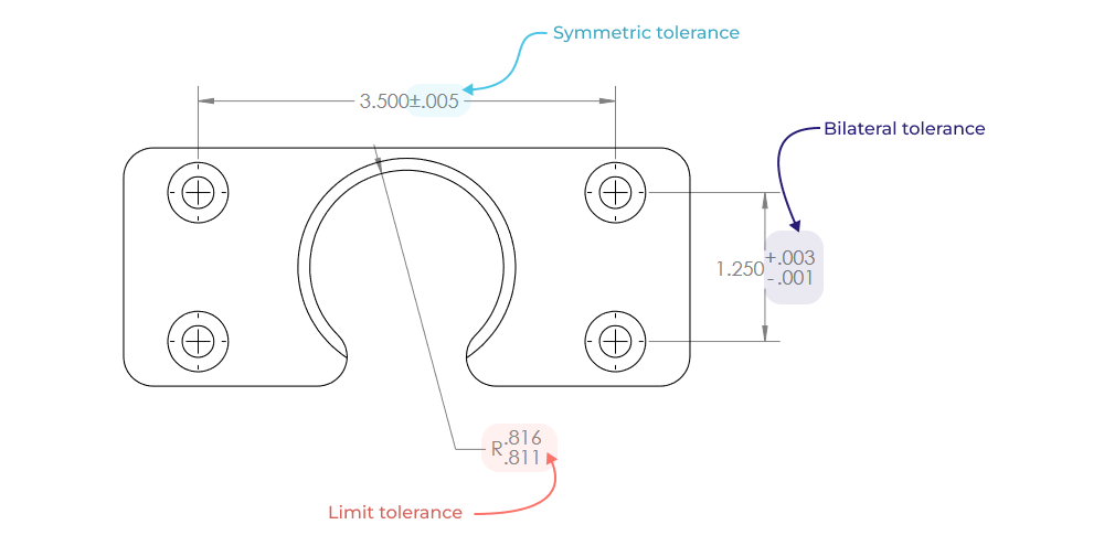
The most common tolerance method is to use symmetric tolerances. Symmetric tolerances establish an upper and lower bound centered around the nominal dimension value (ex: 1.000”±0.005”). Bilateral tolerances are like symmetric tolerances but they are not centered around the nominal dimension (ex: 1.000” +0.003” / -0.001”). Limit tolerances eschew the ± notation entirely in favor of explicitly defining the upper and lower bounds for a dimension. These three tolerance types are shown on the view below.
Note: each of the tolerancing methods you use will have implications on the tolerance stackup calculations. For more info on tolerance analysis you can check out our engineering guide articles and free web calculator:
Intro to RSS tolerance analysis is a great primer on using statistical tolerance analysis methods for product design.
Advanced RSS tolerance analysis is a deep dive on tolerancing for high volume production.
Our free RSS tolerance calculator will let you run RSS and worst case tolerance stack-ups in browser and save/share your results.
Common symbols
There are a variety of symbols used in drawings, many of which are out of scope for the sake of this article. The most common and absolute basic symbols are described and shown on a single drawing below:
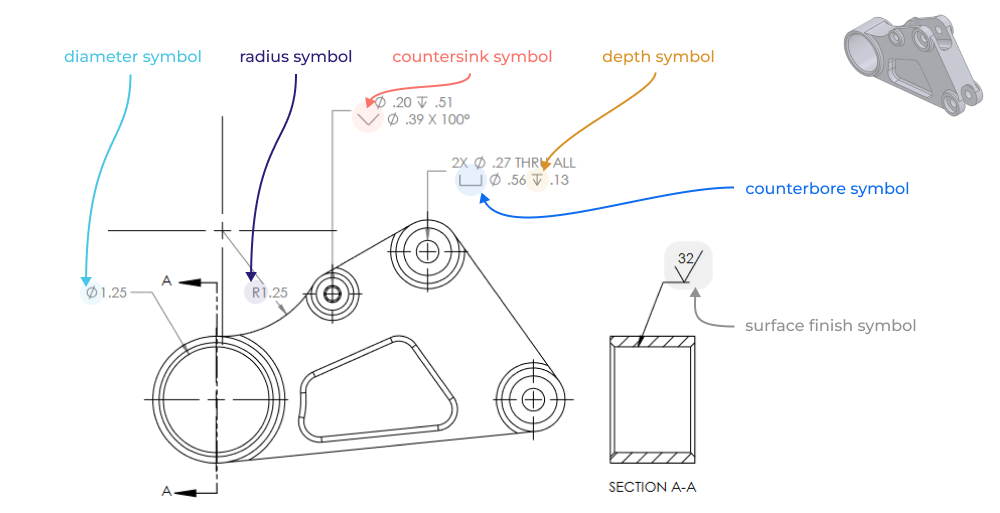
The diameter symbol indicates that a dimension or feature is associated with a diameter (used on holes, bores, arced features, and shafts).
The radius symbol indicates that a dimension or feature is associated with a radius (used commonly on fillets).
The counterbore symbol denotes a counterbored hole.
The countersink symbol denotes a countersunk hole.
The depth symbol indicates the depth of a drilled hole.
The surface finish symbol indicates the surface finish of an entire component or specific face (with leader).
GD&T
GD&T (geometric dimensioning and tolerancing) is a system, standardized by ASME Y14.5, used to convey feature and part specific design intent in terms of both fit and function on drawings. This system goes far beyond linear dimensioning by allowing the creation of feature specific controls and more explicit control of geometric variance of controlled features. Many drawings don’t need GD&T at all, but it is still worth understanding. A complete review of GD&T is way out of the scope of this article, but we will be writing more about it soon! For now the wiki page on GD&T is a great place to start building your understanding.
Drawing notes
Drawing notes should be used communicate auxiliary information not embodied in dimensions and symbols, or to clarify information pertaining to an existing symbolic callout or dimension. This can be as simple as noting what CAD file is associated with the drawing, or as specific as clarifying a required manufacturing step. Don’t be afraid to be specific, and remember that you are always communicating with a human.
Key principles for making great drawings
It can be difficult to evaluate how to develop clear and accurate drawings without an overall framework for understanding drawing quality. Here are a few key principles and best practices to follow when making engineering drawings.
Convey design intent directly
Dimensions
Remember that the purpose of the drawing is to specify geometry in such a way that the design intent of the part is preserved despite the natural variability of all manufacturing processes. This doesn’t have to be complicated! If two holes need to be positioned relative to each other in order to ensure assembly functionality then they should have a corresponding dimension on the drawing (instead of dimensioning them separately from an arbitrary face for example).
Clear notes
Be direct and don’t be afraid to be explicit in your drawings. A short note indicating the intended function of a feature helps machinists and fabricators make better decisions during programming, setup and manufacturing.
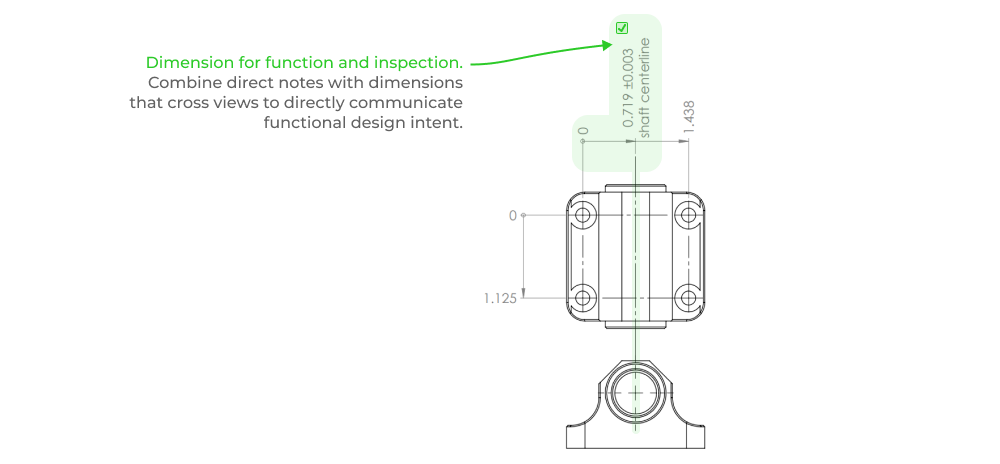
Inspectability
Just as dimensioning follows function, inspection follows dimensions. A drawing with clear dimensions between functional interfaces not only conveys clear design intent, but is also easy to inspect (and cheaper!). The closer the inspection measurements are to functional interfaces, the less likely it is that a part will pass inspection but fail functionally. Wherever possible there should always be a direct thread between inspectability and functionality.
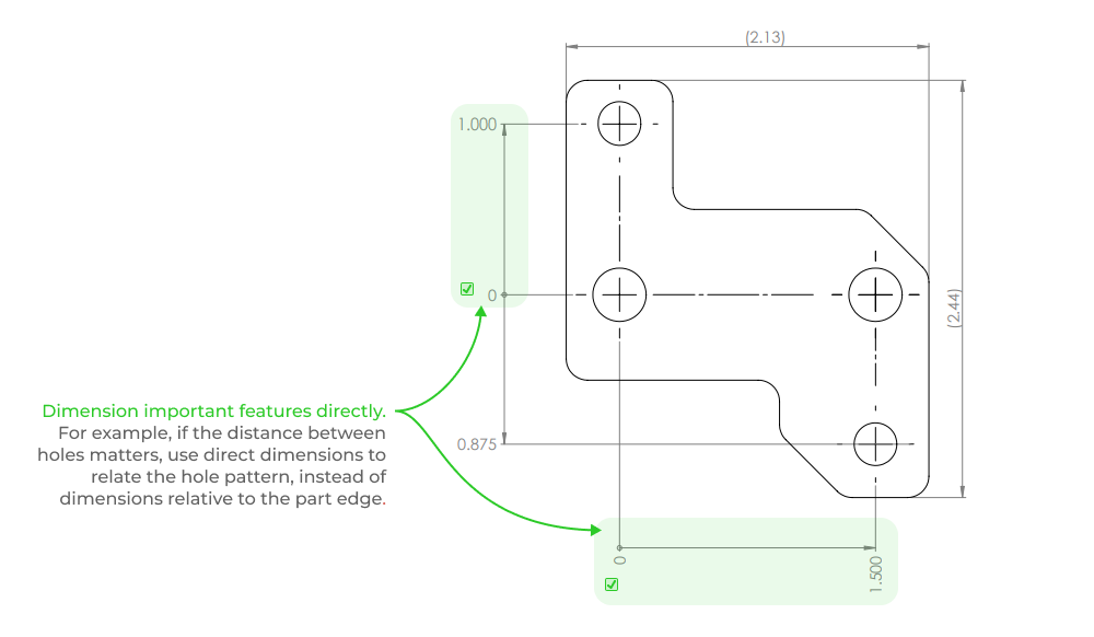
In the part below, the design intent is to align the bearing housing shaft centerline with the mounting holes. A simple ordinate dimensioning scheme is used that connects hole position with the shaft centerline. This tells a machinist what is most important about this part, and what to measure to ensure functionality.
Practical guidance for dimensions
Here are a few tips for dimensioning parts so they are easy to inspect.
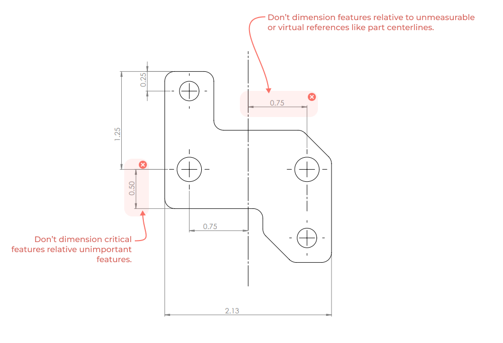
ID important features. This exercise applies to designers and reviewers alike. In all of your drawing views, identify the mating surfaces and other features that define critical interfaces. Think of these as the most important surfaces and all of the other faces as the least important surfaces. See if you can find a direct dimensioning scheme that removes the least important surfaces from the chain of dimensions that define your design intent.
Don’t dimension to non measurable datums. If possible, dimension to a physical feature and not a part centerline or CAD modeling plane. Centerlines and center planes will need to be inferred from other geometry during inspection and this may make in process inspection steps impossible. (notable exception - hole centers)
By dimensioning this way you are telling the person making the part what features and surfaces need special attention and what is less important. Defining what is NOT important can save valuable manufacturing time by allowing relaxed tolerances (and faster manufacturing) in non functional areas.
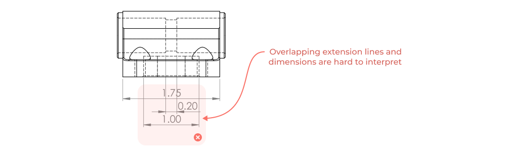
Clarity
This is by no means exhaustive, but here are a few quick tips for making clear and legible drawings.
- Don’t cross dimension lines.
- Don’t dimension hidden lines.
- Use ordinate dimensions when possible.
- Use as many section views, detail views, and pages as necessary to convey design and manufacturing intent without ambiguity... (but nothing more).
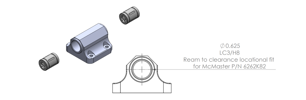
- Write simple and direct notes. These notes should clarify any ambiguity in the drawing or add extra information to convey design intent. (drill bit size, form tap hole, ream to fit, etc..)

- Scale. Add appropriately scaled projected views and use the space you have.
- Include an un-dimensioned isometric view. This view helps communicate 3d at a glance and can be different than the drawing scale used in all other views.
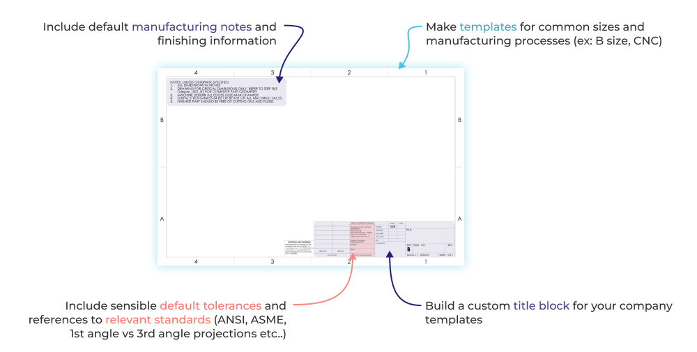
Build reusable drawing infrastructure
Templates
Whatever CAD software you use, be sure to set up drawing sheet templates in the common sizes you will use. These templates should include things like appropriate default tolerances, references to any standards you follow (such as ASME Y14, first vs third angle projection etc…), and drawing borders with alphanumeric grid lines.
Manufacturing notes
Different manufacturing processes have different impacts on part functionality and design intent. It’s a good idea to have standard drawing notes for each manufacturing process. If these aren’t included at the template level, having a central location where engineers can easily copy and paste in the latest drawing notes is a huge time saver.
Title blocks and default tolerances
Set up a good title block for your company with appropriate default tolerances. Over-specifying tight tolerances is a path to wasting money and driving your manufacturers crazy. Consider how default tolerances should be applied for the types of parts you design and set them conservatively. It can sometimes be useful to create templates per manufacturing process so that default tolerances can be set appropriately and process specific drawing notes can be included in templates.
Pages and views are free - use them!
With modern CAD programs, the cost of adding an additional page or view is trivial. You should absolutely take advantage of this! Auxiliary, section, and detail views should be used freely to directly display feature specific information that is not available in other views. Eliminate redundancy across views wherever possible and be sure to leave out views that don’t add any new information.
Don’t be afraid to show the same view (ex: front view) on different pages, as long as different features are called out across the views. This can be a great way to keep individual sheets from becoming too busy. For example, one view of a part might include hole callouts and an associated hole table (and that’s it!). While another page with the same view might include exterior dimensions (such as form and profile information) along with high level manufacturing information for your machinist (ex: reference dimensions for stock size calculation, estimated part weight, outside dimensional tolerances etc…)
Five Flute - Next generation collaboration for hardware product development
If you are a design engineer or technical project manager and you want to design better products in less time, consider Five Flute. It’s the fastest way to share, review, and improve your engineering designs. From engineering drawing reviews to 3D design reviews of complex parts and assemblies, Five Flute is built for modern engineering teams that want to move faster without making mistakes.