In this introductory article we will be equipping you with a foundational understanding of geometric dimensioning and tolerancing (GD&T) so that you can apply it to your part designs. We’ll be covering the following:
- What is GD&T and how does it help?
- Getting started with datums - understanding datum reference frames and datum features
- Tolerance zones and feature symbols
- Basic dimensions
- Building feature control frames
- introduction to material condition modifiers
- Inspection
What is GD&T and how does it help?
Geometric dimensioning and tolerancing (GD&T) is a system for defining and communicating both the desired nominal dimensions and the allowable geometric tolerances of manufactured parts. GD&T establishes a shared symbolic language that can be used on engineering drawings and computer-generated three-dimensional solid models that explicitly describe nominal geometry and its allowable variation. In doing so, GD&T provides a precise and comprehensive means for defining parts and assemblies, allowing manufacturers and inspectors to ensure that they are produced consistently and accurately. It is an international standard that is used in almost every industry, including aerospace, automotive, and medical devices.
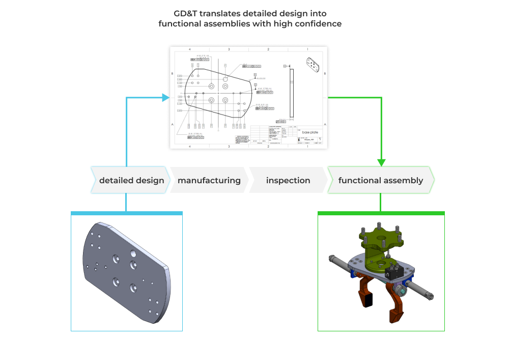
Simply put, GD&T helps transform design intent into functional manufactured output.
Primary benefit and pros/cons
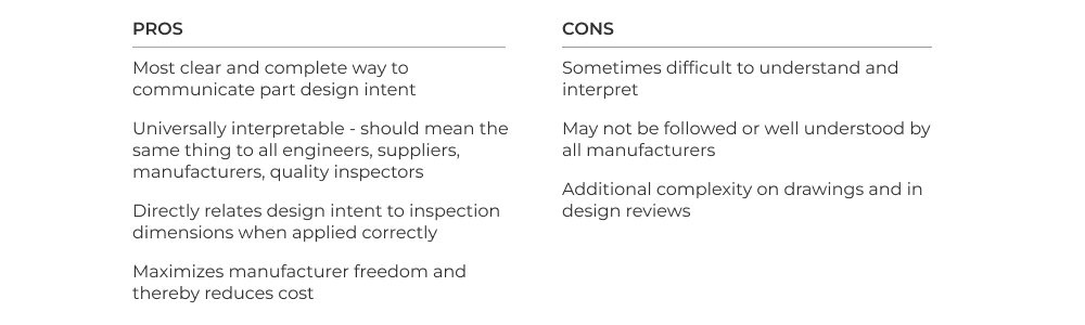
The primary benefit of GD&T is that it ensures your design intent is specified and communicated in such a way that you guarantee proper part function in the assembly context. For complicated assemblies this is daunting process, but GD&T gives you a language and a rule set to do so, but it is not without cost. The table below highlights the pros and cons of GD&T at a high level.
GD&T is a language and rule set
GD&T is standardized by the ASME Y14.5-2018 Dimensioning and Tolerancing standard. This standard lays out, in exhaustive detail, all of the ways that part geometry can be controlled in drawings. The important thing to know is that GD&T is a set of basic rules and an associated symbology that define a language for specifying geometry and geometric variance. You don’t need to memorize every symbol, but you should have a framework or mental model for how it works. Before we dive into the symbols and their application, you need to understand how ideal part geometry is communicated. That leads to the concept of the datum reference frame and datum features on your parts.
Getting started with datums - understanding datum reference frames and datum features
The foundational question that datum reference frames and datum features help us answer is, what do we measure against? If every face and feature of a manufactured part is not perfect, how do we use relative and absolute measurements to check the part? We need to establish a universal way to check all of the features and their associated dimensional tolerances. That’s where the concept of the datum reference frame comes in handy.
Datum reference frames
In GD&T, the datum reference frame (DRF) is an important concept because it defines the coordinate system in which all other dimensions and tolerances are specified. This allows for the use of geometric tolerances, which are tolerances that specify the allowable deviation of a feature from its ideal shape or orientation, rather than just specifying the allowable deviation of a single linear dimension. Here’s the definition:
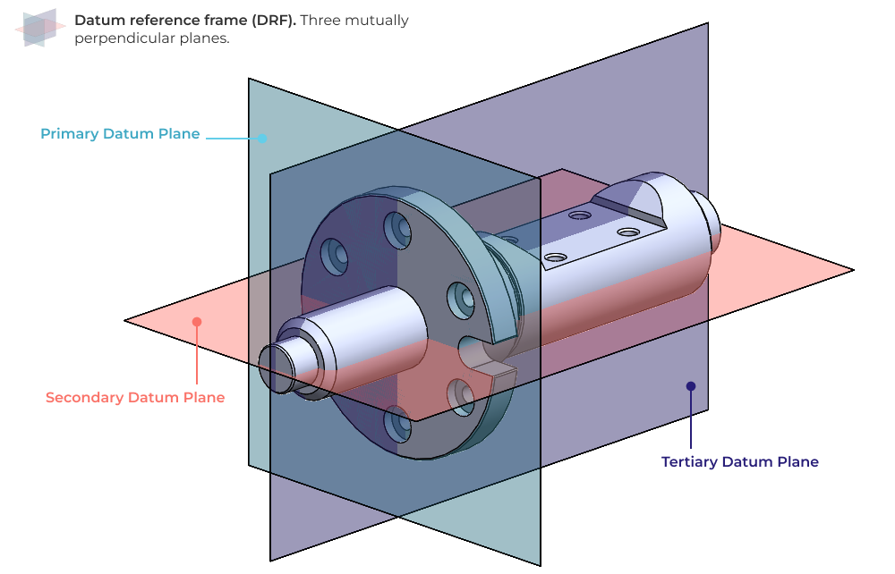
The datum reference frame (DRF): A datum reference frame is three mutually perpendicular intersecting datum planes**.** The datum reference frame establishes a shared set of orthogonal planes that is leveraged by all subsequent feature controls and tolerances that you specify. Without a properly constructed DRF, your feature controls may not communicate your design intent.
Datum features
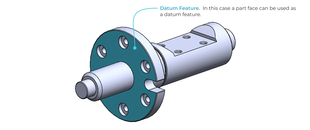
In GD&T, a datum feature is a physical feature on a part that is used to establish a datum reference frame (DRF). It’s important to remember that datum features refer to actual part features; things like faces, edges and vertices.
Building a datum reference frame
A DRF is composed of three datums: primary, secondary and tertiary datum planes. These datums are defined by selecting datum features on the part (note: the datum features do not necessarily have to be planes themselves). The simplest possible DRF is defined by three orthogonal part faces, as shown on the prismatic part below.
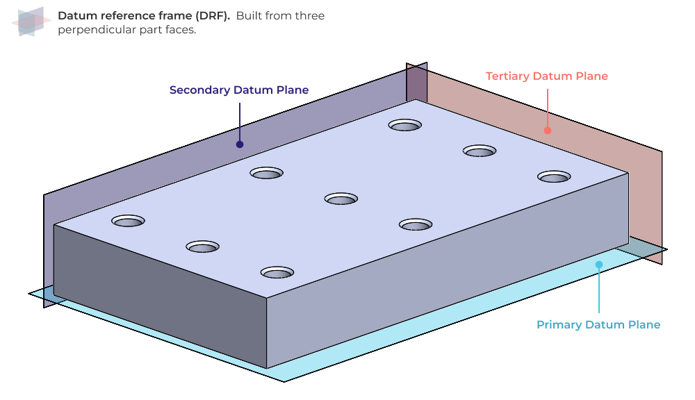
*Pro tip: For more on selecting datum features and constructing datum reference frames check out our Mastering GD&T: Building Datum Reference Frames article.*
Feature controls, tolerance zones and feature symbols
Now that we have a DRF to measure against, we need a way to control the geometry of the part. GD&T uses a language of symbols to establish feature controls with associated tolerance zones that define the allowable geometric variation of the manufactured part.
Tolerance zones
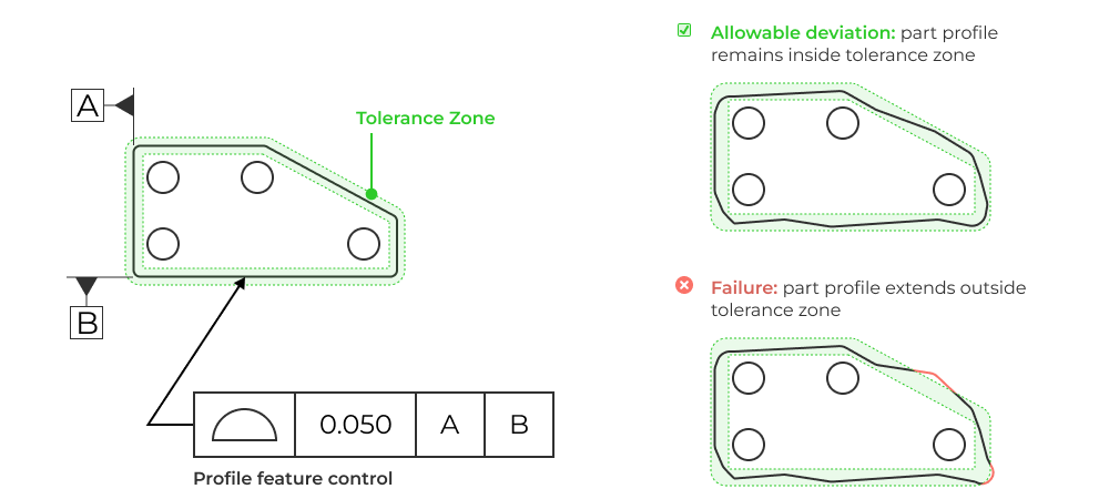
Before we go over the various symbols to define geometry controls, it helps to understand tolerance zones with a simple example. A tolerance zone explicitly defines where and how part geometry is permitted to vary. It does this by setting limits, usually in the form of boundaries, within which the controlled feature must remain.
Lets look at the tolerance zone for a controlled part profile. In a part with a simple 2D profile, the tolerance zone is constructed by offsetting the part profile inward and outward to establish minimum and maximum material boundaries. The manufactured part profile must lie within this tolerance zone.
Symbols
GD&T feature control symbols are used to establish different types of tolerance zones, each tailored toward ensuring different aspects of part and assembly functionality. Some of them require datum features to reference in order to use properly. For example, position requires datums in order to locate a hole center within a cylindrical tolerance zone.
Other control symbols do not require datums. Flatness for example, controls the relative high and low spots of a single face. Given that the geometric control is self referential (concerned with a single face only), no additional datums are required.
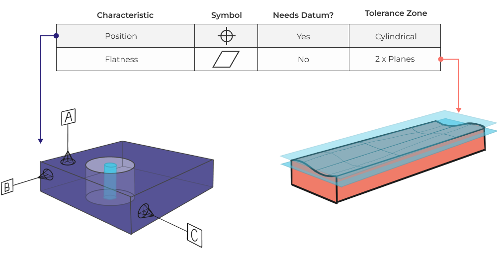
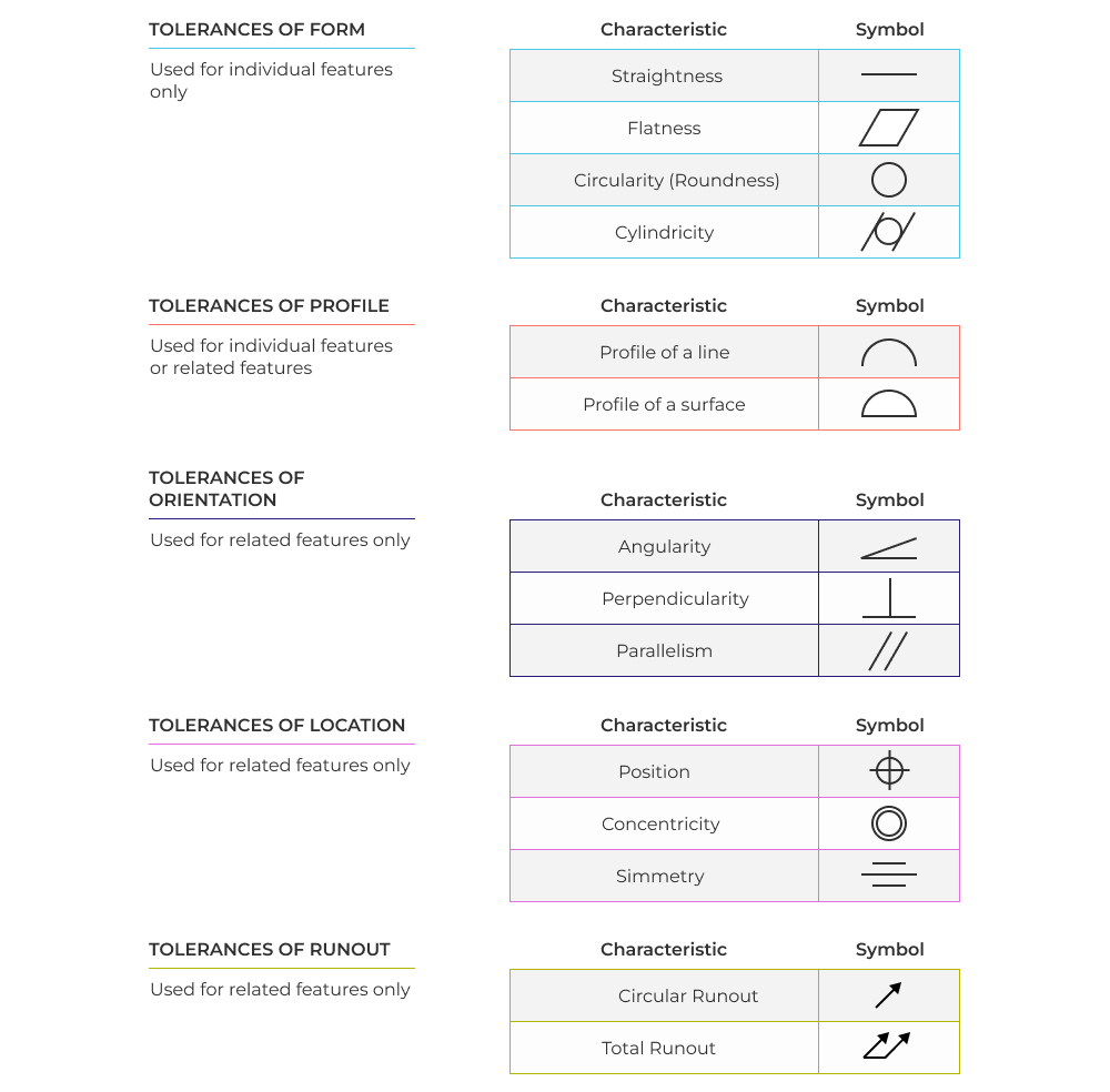
Here’s a summary table showing each feature control symbol.
Feature control frames
In GD&T, feature control frames (FCF) are the notation used to control geometry. They leverage datum features, tolerance symbols, tolerance values, and other clarifying symbols to define how geometry is controlled. Here’s a visual overview of a simple feature control frame that specifies the position tolerance of a hole in a prismatic part.
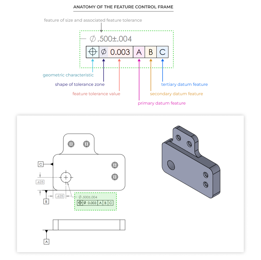
Note that the feature control frame is attached to an existing dimension and tolerance, that is the feature that the control frame is controlling! Each FCF controls only a single feature with a single feature characteristic. You can use multiple control frames (typically stacked vertically) to control multiple characteristics.
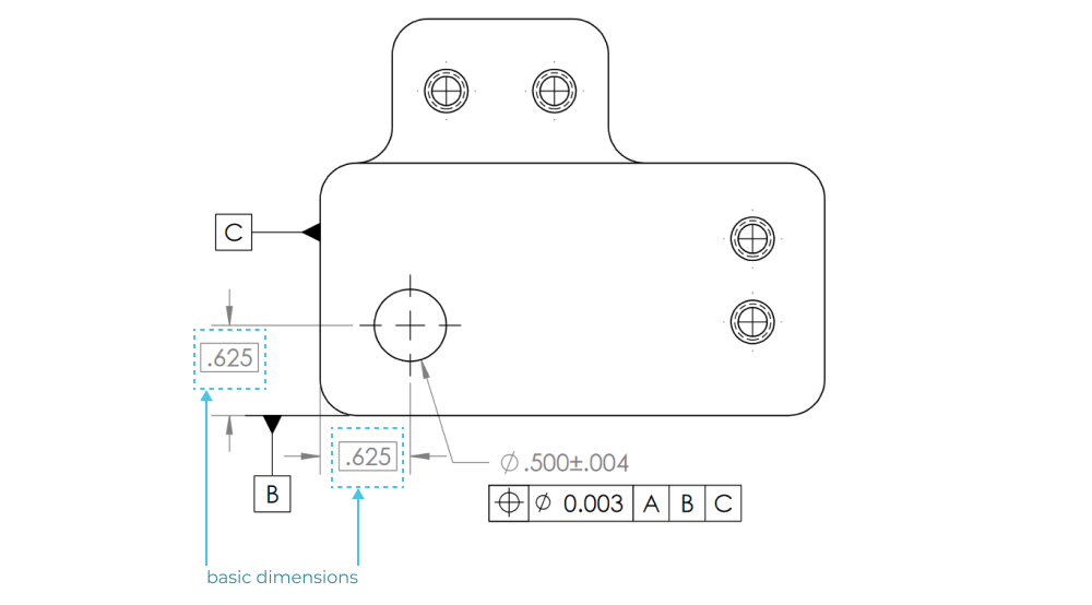
Basic dimensions
Simply put, a basic dimension is a theoretically exact dimension. Why does this matter in GD&T? It matters because for many features (e.g. hole patterns) you no longer need to specify a linear dimension in X and Y with an associated ± tolerance. The features are instead controlled by feature control frames with a variety of tolerance zones. Basic dimensions, therefor, indicate the idea or perfect geometry of the final manufactured part. They are not inspected directly typically, because there is not a clear pass/fail criterion associated with each dimension. Additionally, the drawing title block tolerances do not apply to basic dimensions.
To create a basic dimension you can use a box around the dimension.
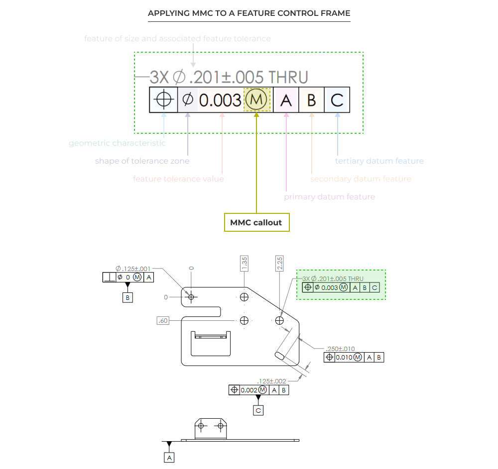
Introduction to material modifiers
Material modifiers (sometimes called material condition modifiers) are a powerful but extremely tricky aspect of the GD&T toolkit. Material modifiers give you the ability to specify geometric controls and associated tolerance values that are conditionally related to the actual as-manufactured part geometry. Practically speaking, material modifiers let manufacturers know that certain tolerances can be increased or decreased based on the size of other geometry.
Consider a common design case where you have two components with matching bolt patterns. You want to be sure that assembly is possible. Practically speaking it’s easy to see that if the clearance holes are under drilled (smaller diameter than nominal), the positional tolerance needs to be tighter in order to ensure consistent assembly.
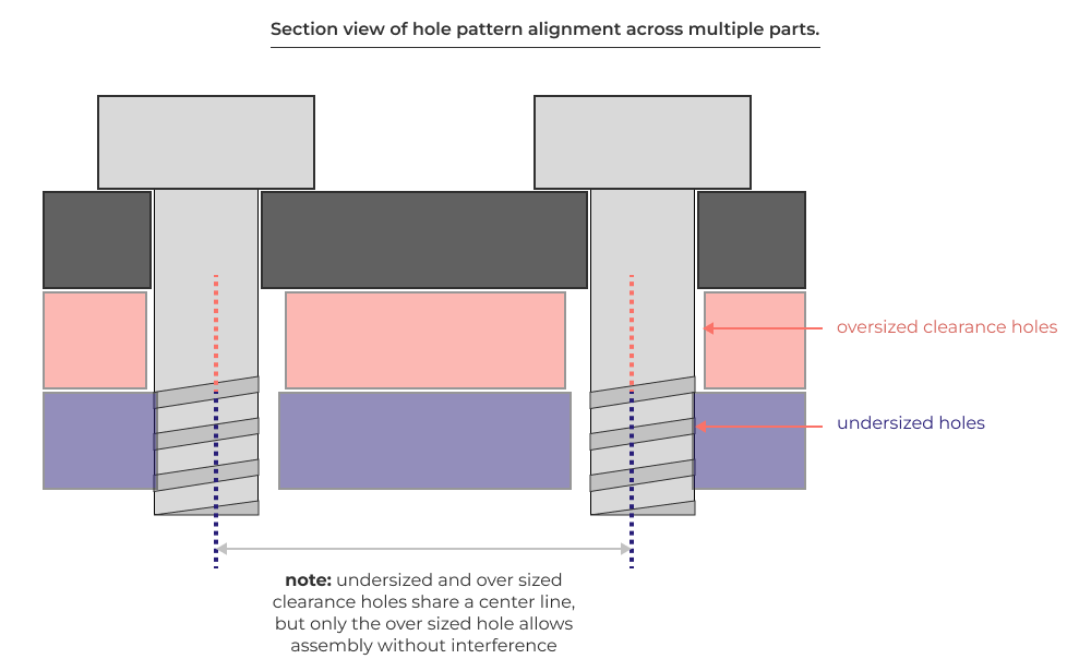
Material modifiers give you the ability account for situations like this by specifying geometric characteristics that consider this kind of real world manufacturing output (holes are smaller or larger than nominal).
RFS, LMC, & MMC
There are three concepts to understand when applying material modifiers.
Regardless of Feature Size (RFS). This is the default behavior of a feature control frame. It means that the geometric control is applied regardless of any differences in the size and shape of other part features.
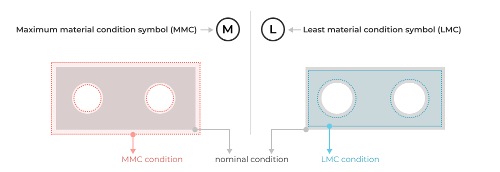
Least Material Condition (LMC). This means that the feature control is most critical when the part is in a least material condition, or smallest allowable size. LMC means a smaller part volume. For exterior features this means the overall bounding box of the part is smaller. For interior features like holes for example, the LMC condition actually means a bigger hole. Remember that we are referencing material volume, not feature size!
Maximum Material Condition (MMC). This means the opposite of LMC. At MMC, parts have maximal volume. The exterior boundary envelope is as large as allowable, and any pockets, voids, or holes are as small as permissible.
Symbols for the application of RFS, LMC, & MMC in feature control frames
Since RFS is the default condition, there is no symbol to call it out in the feature control frame. To specify LMC and MMC you can use the following symbols.
Here’s what it looks like in a feature control frame on an example drawing.
Inspection
None of the GD&T is worth it unless it can be verified that a specification is met; that’s where inspection comes in. The key thing to remember is that verification of GD&T specifications can only take place by constraining the part in a manner consistent with the chosen datums, and using commonly available measurement methods in the form of both fixed and variable gages. As a part designer, it’s important to have practical knowledge of datum feature simulators and common measurement equipment. This will inform your choice of datum features when applying GD&T.
Constraining parts with datum feature simulators
During inspection, proper measurement relies on proper part orientation and constraint of the part relative to measurement equipment. GD&T defines a datum feature simulator as the inverse shape of a datum feature. What this really means is that during inspection you need a way to hold and support the part during measurement, and way to represent ideal feature specific geometry.
The simplest and most common datum feature simulator in machine shops is an granite surface plate.
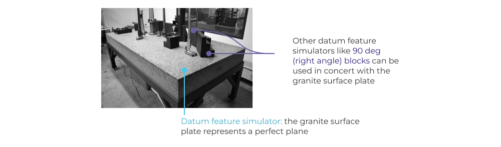
The granite surface plate acts as the inverse of a simple datum plane (which is itself just a plane). There are many different kinds of datum feature simulators (both physical and theoretical), but the important thing is that they share some fundamental properties that make inspection and verification of feature controls possible.
Primary requirements of datum feature simulators
- Perfect form! This means they need to be accurate enough that you can measure against them. If you granite surface plate is no longer flat, you won’t be able to verify a flatness or parallelism feature control.
- basic orientation relative to one another for all the datum references in a feature control frame. This means that the datum feature simulators must have the proper relationship (in terms of orientation and alignment) to each other in order to enable verification of features that reference multiple datums.
- basic location relative to other datum feature simulators for all the datum references in a feature control. This is similar to number 2, but is concerned with exact positioning of datum features instead of just orientation.
There are other requirements, but the top three focus on solving the primary measurement problem; In order to measure accurately, you need a representation of perfect geometry. Datum feature simulators provide this perfect geometry. To get a sense for the care required maintain a high quality datum feature simulator you can check out this Tom Lipton video on calibrating and conditioning granite surface plates.
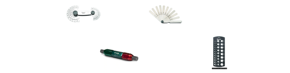
Fixed Gages
Fixed gages are used to measure a specific feature and that feature alone. Common fixed gages include:
- Pin and plug gages (go/no-go)
- Drill and wire gages
- Radius gages
- Angle gages
- Screw pitch gages
- Thickness gages
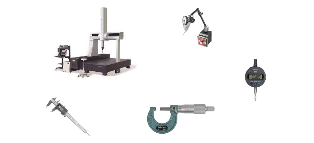
Variable Gages
Fixed gages are used to measure a wide range of features and sizes. Common variable gages include:
- rulers
- calipers
- dial indicators
- micrometers
- coordinate measurement machines
Final Thoughts
GD&T can feel daunting, cryptic, and hard to learn, but it only relies on a handful of key concepts. You can always bookmark this page to keep it handy as a refresher on these basic concepts. Practically speaking the detailed application of GD&T can be learned/refreshed on the fly while designing parts and making drawings. It’s sufficiently complicated that a drawing review process becomes a necessity.
Five Flute - Next generation collaboration for hardware product development
If you are a design engineer or technical project manager and you want to design better products in less time, consider Five Flute. It’s the fastest way to share, review, and improve your engineering designs. From engineering drawing reviews to 3D design reviews of complex parts and assemblies, Five Flute is built for modern engineering teams that want to move faster without making mistakes.
You might also be interested in
Mastering GD&T: Building Datum Reference Frames
Five Flute drawing review checklist
Drawings 101 - The basics of creating high quality engineering drawings