Waterjet cutting is one of the most flexible and capable manufacturing methods available to mechanical engineers. Despite the relative simplicity (most machines cut 2D geometry only), waterjet machines are a Swiss army knife for rapid prototyping. In this article I’m going to cover the basics of how waterjet machines work before diving into the most useful design patterns that leverage waterjet cutting for rapid prototype development. Finally, we’ll close with some practical guidance for manufacturing preparation and DFM.
How waterjet machines work
A waterjet cutting machine uses a high-pressure stream of water (50,000 psi or greater!) mixed with abrasive particles (typically garnet), to cut through various materials. The water is forced through a jewel orifice (diamond, ruby, or sapphire), which allows it to cut through materials such as metal, stone, and glass with accuracy, precision, and essentially zero heat damage. Waterjets are CNC machines that follow a programmed path (most often generated from a .dxf file) in order to cut the desired geometry.
Advantages & disadvantages
Advantages
- Waterjets are material agnostic! They can cut through materials as tough as tungsten, tool steel, and titanium, or as soft and delicate as polypropylene or leather. The process generates negligible amounts of heat making it ideal for cutting heat treated materials without annealing them.
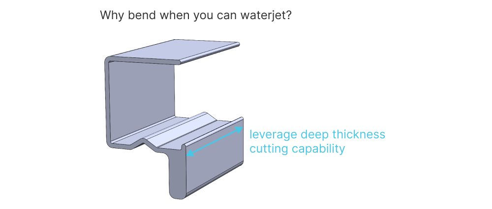
- High material thickness cutting ability. Waterjets can cut through 8” thick blocks of aluminum and even thicker in softer materials. This gives you a lot of flexibility when prototyping if used creatively.
- Low cost setup, fast programming. Waterjet is a great process for rapid prototyping because there is effectively no tooling involved. Just slap a large plate down on the bed of the waterjet and start cutting parts. Programming toolpaths is incredibly fast when a proper .dxf file is prepared for manufacturers.
Disadvantages
- Edge finish quality can be pretty ugly compared to CNC and other machining processes. You can slow down waterjet machines to get better edge surface finish, but ultimately it doesn’t come close to machining. This article covers edge quality ratings at a high level.
- Relatively poor tolerances compared to machining. Some shops are capable of hitting a ±0.003 tolerance if you absolutely need it, but more commonly you can expect profile defects on the order of ±0.008 with most manufacturers.
- Inability to cut 2.5D and 3D geometry (most machines).
Most Useful Waterjet Design Patterns
Here are some of the most useful design patterns leveraging waterjet cutting that you can apply to your rapid prototyping and product development projects today.
Cutting thick parts
The unique ability of waterjets to cut extremely thick plate in a variety of materials allows for some pretty creative applications. One of my favorites is to waterjet cut parts that would otherwise be created as bent sheet metal components. Components like clips, simple sheet metal brackets and springs can all be cut directly on waterjets without post processing. Here’s an example spring clip part.
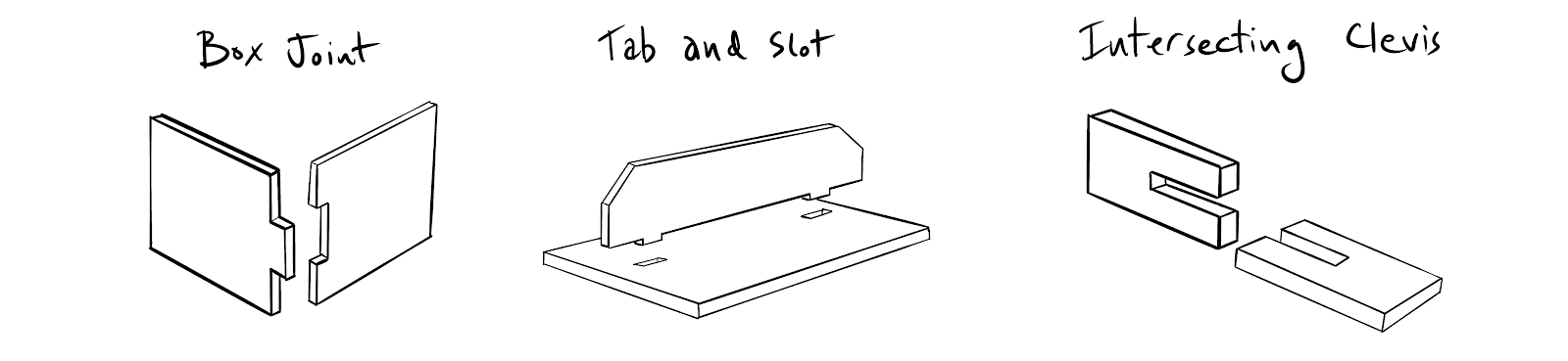
Weldments with integrated tab fixturing
Waterjet cutting is really useful for prototyping fabricated or glued structures. Integrated tabs allow accurate registration between parts before gluing, welding or fastening. A few examples are illustrated below.
When using this method, remember that internal corners on tabs and slots may have a small kerf radius that must be accounted for to ensure accurate alignment.
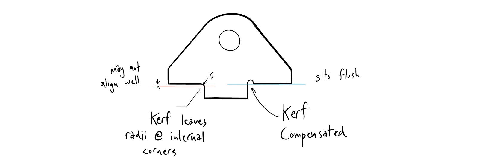
We elaborate on this in our Practical DFMA article.
Flexures
Waterjets allow you to rapidly prototype monolithic flexure assemblies. This is a super cheap way to make high accuracy linear positioning systems (great for optics and measurement projects). Check out this Dan Gelbart video and this MIT resource for a great set of primers on the topic.
Rapid production of high accuracy jigs and fixtures
There are two extremely useful design patterns that you can use for building accurate assembly fixtures and manufacturing jigs.
Combine waterjet sheets with T-slot framing
Waterjet plates combined with T-slot framing from McMaster will allow you to make extremely accurate and stiff test and assembly fixtures. The waterjet plates can act as both an assembly guide (making it easy to know where to attach T-slot rails), a shear resistant stiffener, and an integrated structural mount for non T-slot components.
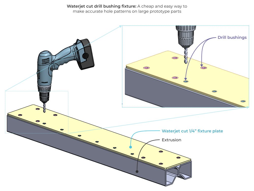
Waterjet jigs with press fit drill bushings
Many components have accurate hole tolerance requirements, but few other constraints in terms of machining. You can use waterjet plates with press fit drill bushings to make extremely accurate and cheap drilling jigs. This works especially well with large extruded components that would otherwise require costly machining setup just to drill a few holes.
Instead, try waterjet cutting a 1/4” Aluminum plate, reaming the holes on a drill press, and pressing in drill bushings. Then you can simply clamp your fixture plate to your material and drill a set of highly accurate holes with a handheld drill.
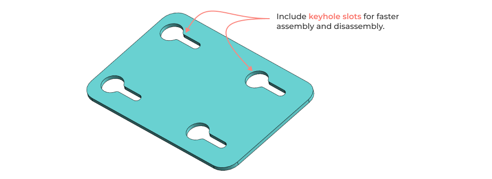
Keyhole slots for easy assembly
Waterjet cutting makes all 2d geometry effectively identical in cost. One of my favorite rapid prototyping patterns with waterjet cutting is all about making assembly and disassembly fast. Instead of cutting holes in your parts, cut keyhole slots. Make sure the large diameter of the keyhole is big enough to clear your fastener head diameter. This makes assembly and disassembly of matched bolt pattern components extremely quick. It’s great for quickly “hot swapping” components in modular test setups.
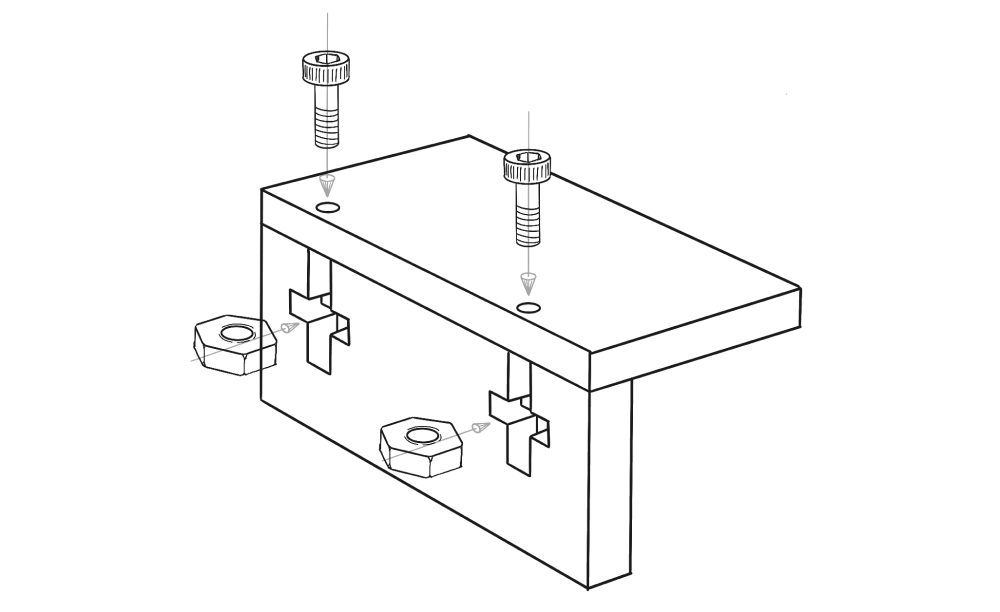
Tab and bolt assembly
Similar to the weldments design pattern, waterjet cutting a set of matching tabs and nut holders allows you to quickly bolt plates together at 90 degree angles.
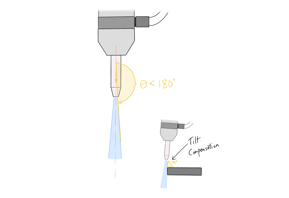
Note: remember to keep in mind the angular spread of the waterjet when leveraging this method. For this technique, I’d recommend finding a waterjet manufacturer with a tilt compensation setup (or 5 axis machine) that ensures the cuts will result in a 90 degree angle.
Abrasive free cutting
Waterjet machines can run just as well without garnet abrasive. This makes them well suited to cutting soft materials with a nice clean edge. I’ve used this technique to cut accurate rubber seals and gaskets from silicone and buna-n rubber sheet. Garnet free cutting also works well with open cell foams, making it easy to prototype packaging materials. Waterjets are even used to cut fish fillets in manufacturing.
Cutting composites
Any machinist will tell you that cutting multi-ply composites is a headache. Delamination, tool wear, and fixturing are all issues. Waterjet cutting can be used very successfully to cut composite materials, as long as it is combined with a good strategy for cut initiation (like pre-drilling at the jet piercing locations). I’ve used this to cut insulating washers, gaskets, and panels from NEMA G10 fiberglass. This great article covers some of the pros and cons of using a waterjet to cut carbon composites.
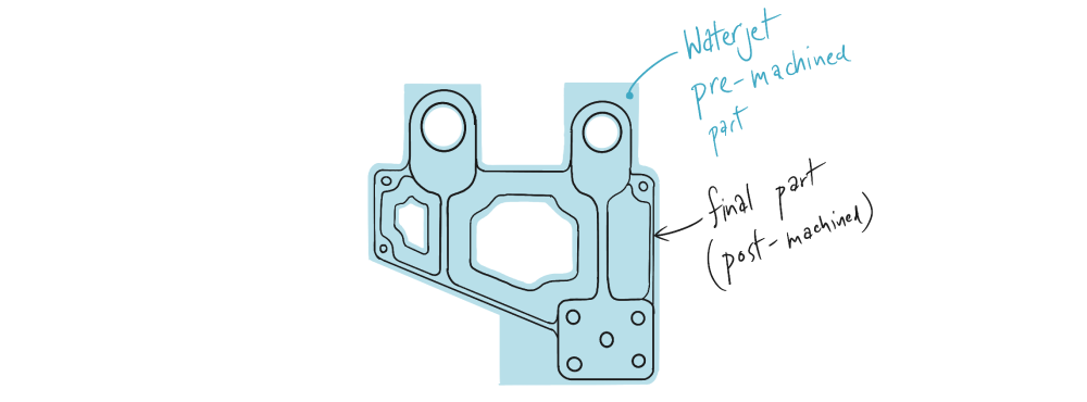
Preprocessing for large CNC components
Larger machined components (i.e. aerospace prototypes) that have significant material removal can often be prototyped very efficiently by first waterjet cutting a net near shape profile and then finish machining critical features. This can be a great intermediate production step for components that will ultimately be cast and post machined.
Dealing with manufacturers and practical DFM
Here are some practical tips for dealing with manufacturers as well as some DFM guidance for waterjet components.
Drawing file preparation
Waterjet machines are programmed from 1:1 scale drawings in .dxf format. The software used to generate the G-code typically does not interpolate splines very well, so its best to include only lines and arcs in your DXF. To make programming even easier, it can be helpful to provide two separate drawings to your manufacturer.
- A clean 1:1 scale flat pattern .dxf file with no drawing border, hole center marks and centerlines or any other annotations. You want a programmer to be able to quickly select all lines in the drawing as valid geometry for toolpath generation. Be sure that all of your desired features are modeled to size. For example, if you want a 0.252” diameter hole, don’t model the hole as 0.250” and rely on a dimension on your attached drawing. Instead make the part true to size and rely on your 1:1 scale .dxf to communicate geometry.
- (Optional) A separate dimensioned drawing for critical to function dimensions. This is important if you have holes or other features that you want post machined. A drawing with tolerances and notes indicated separately machined features makes it clear to your waterjet manufacturer what needs to be cut with each process.
Tolerances
(Note: your mileage may vary, always talk to your manufacturer about tolerances)
Waterjet machines have approximately 0.001” positioning accuracy and even better repeatability. They are CNC controlled so machine accuracy only plays a small part in terms of final component tolerances. The combination of cutting speed and the control of the abrasive jet geometry are the primary factors in finished component tolerance.
Generally speaking, tolerances of ±0.005” are achievable without much impact on cost. Optimistically, tolerances of ±0.003” are achievable if your manufacturer takes good care of their nozzles, is willing to slow down cut speeds and dial in final geometry. As a designer it can be helpful to design for tolerances on the order of ±0.008” - 0.010” conservatively.
Kerf and taper
Due to the fundamental physics involved, waterjet machines cut material with a conical shaped jet. For basic 3-axis machines this results in edge taper on finished parts. For thin sheets this is negligible, but this taper can be significant when cutting thicker materials. Some machines can compensate for this conical jet geometry by tilting the cutting head.
Talk with your manufacturer about their machines and the edge quality requirements for you parts. Note that the introduction of a tilt compensating jet head may result in worse profile tolerances because the height of the sheet stock on the bed is now coupled with X-Y dimensional accuracy.
Cost cutting
To reduce the cost of your waterjet parts focus on the following:
- Specify and clearly communicate your finish requirements. If you can accept a worse finish then you are effectively giving permission to your waterjet manufacturer to run the jet at faster cutting speeds. This results in less machine time per part and lower cost.
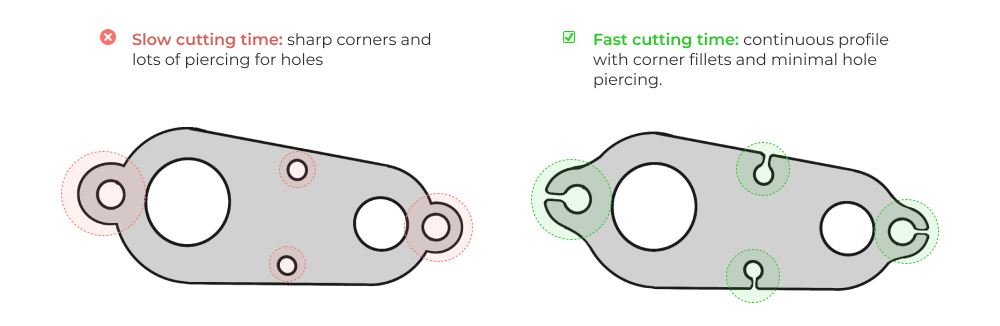
- Avoid sharp corners. Sharp corners require tool head accelerations that slow down cutting speed and impact profile tolerance.
- Reduce piercing. Design your components to limit interruptions in continuous cutting. Piercing (to create holes for example) is a more costly operation than continuous linear cutting. If possible, consider linking geometry to maximize linear cutting distance and minimize piercing.
Closing thoughts
Waterjet cutting, when creatively used, can help you speed up your prototype development. It’s flexible, fast, accurate, and cheap. If your first thought when prototyping is to lean on 3d printing and CNC machining, consider modifying your designs to work well with waterjet cutting. You may end up trimming weeks off your schedule, discovering more issues earlier in development, and ultimately iterating faster.
Five Flute - Next generation collaboration for hardware product development
If you are a design engineer or technical project manager and you want to design better products in less time, consider Five Flute. It’s the fastest way to share, review, and improve your engineering designs. From engineering drawing reviews to 3D design reviews of complex parts and assemblies, Five Flute is built for modern engineering teams that want to move faster without making mistakes.
You might also enjoy
Practical Design for Manufacturability and Assembly
The Five Flute Tolerance Analysis Calculator
Mastering Drawings - Top Tips for Creating Better Sheet Metal Part Drawings