Sheet metal parts often require multiple manufacturing processes to produce correctly. Because of this added complexity sheet metal drawings can be particularly tricky to create. This article will focus on how to prepare accurate and easy to interpret sheet metal drawings so that your parts come out in spec every time. As a bonus, the best practices included in this article can help you establish a better working relationship with your manufacturers and reduce extra workload associated with translating an imperfect drawing into a fabricated component.
Start by understanding design for manufacturability (DFM)
In this section we will be considering four foundational DFM considerations in order to create great sheet metal drawings.
- Manufacturing process mapping
- Flat pattern process considerations
- Bending specific design considerations
- Default tolerances
Manufacturing process mapping
Sheet metal parts require a sequence of manufacturing processes to transition from raw stock material to finished part. The first step in design for manufacturability is to consider this sequence of manufacturing steps and the design constraints associated with each process. Consider a low volume computer enclosure component. If the intended flat pattern is waterjet cut and then bent using a CNC press brake, what does that imply in terms of edge to bend accuracy? How will that stack up across all bends in the part? If the part is powder coated what hole diameter ranges will be acceptable for final assembly? These considerations can only take place after process steps have been clearly thought through.
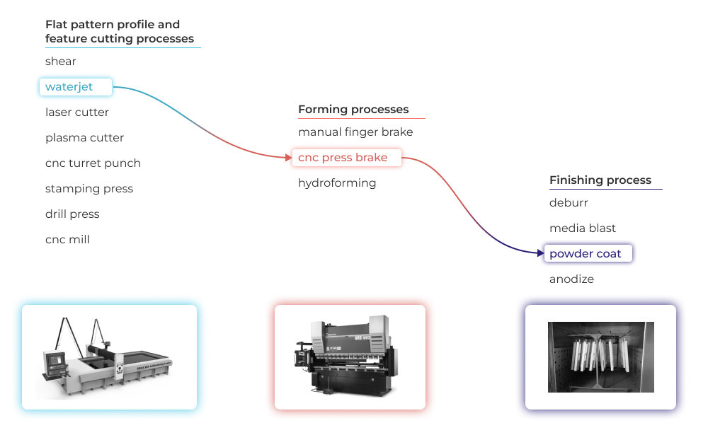
Flat pattern process considerations
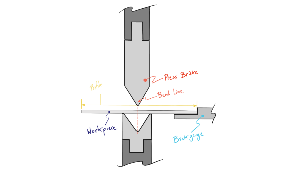
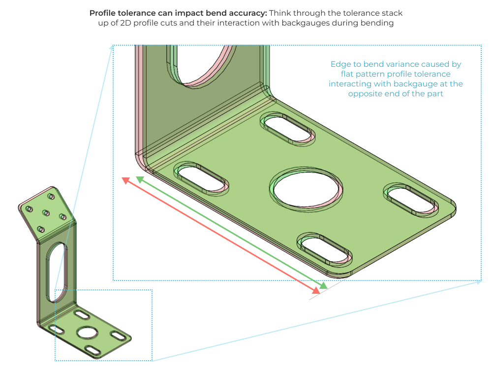
The first step in any sheet metal component is to transform sheet stock into a part profile suitable for bending. A variety of different processes are suitable for this process, and you’ll want to be sure you consider the DFM implications of each. Remember that bend stops and backgauge fixtures indicate off of the part profile, so this process can have impacts on bend accuracy that stack up significantly.
Consider also that certain processes favor specific cut geometries which can have large price implications. For example, cnc turret punch press machines have standard tooling that make cutting certain geometries very inexpensive. More custom shapes may warrant extra processing or the development of custom tools to manufacture at volume. On the other hand, laser cutting can cut any 2D pattern as long as laser kerf width is considered appropriately. The bottom line is you should talk to your manufacturers about their capability early in your design process in order to save time and money.
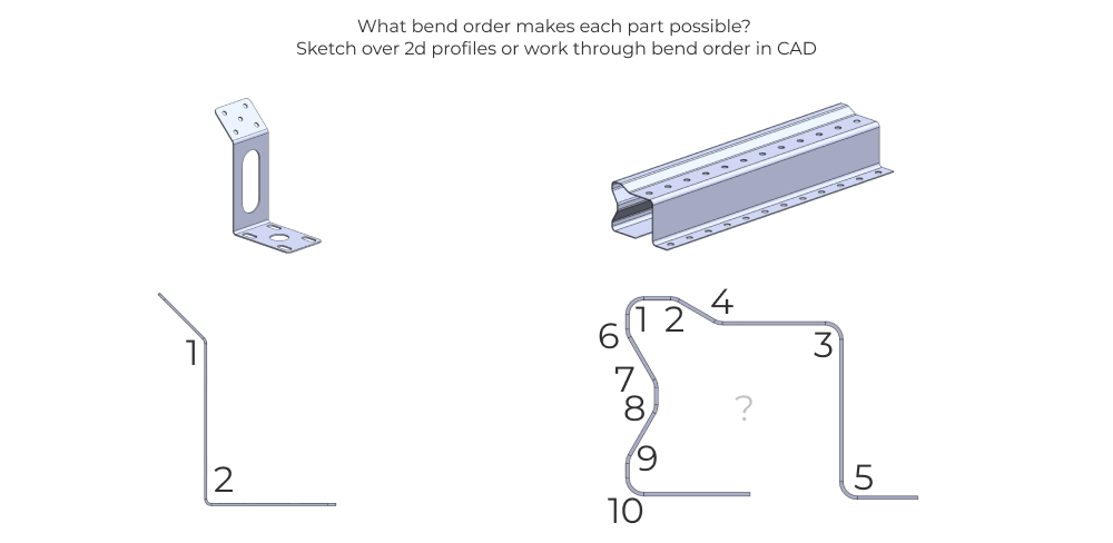
Bending specific design considerations
Here are a few of the key design considerations for formed and bent components. Note this is written primarily for manual and cnc press brake bent part designs formed from a pre-cut flat pattern.
-
Think through the bend features and bending order implied by your design and determine roughly if it is feasible with standard tooling.
-
Consider the thickness of your material and crosscheck against allowable bend radii for each feature. This article from The Fabricator touches on material bend radius concerns and is definitely worth a read.
-
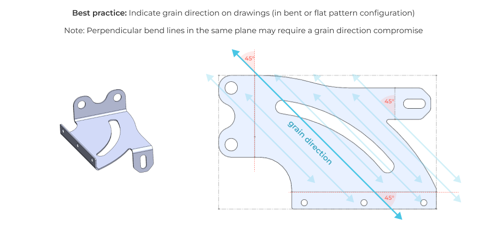
Understand how grain direction must be aligned relative to bends (you will need to note this on your drawing). This is particularly important for stainless steel and some aluminum alloys with large material grain size. Large grain structure and the sheet rolling process can give the material anisotropic strength properties which can cause bends across short grains to fracture as compared to bends across long grains.
-
Bend allowances should not be an afterthought. All bend processes introduce material deformations that must be compensated for in flat pattern construction. The wikipedia page on bending gives a great primer on this topic. As a designer, you should understand that the K-factor for a particular bend-material combination is a roll-up of unknown error sources. This makes it difficult to predict initially. Often, manufacturers iterate bend parameters and flat patterns until each bend falls in spec in terms of dimensional accuracy and spring back. We will touch more on this in the File preparation and manufacturer collaboration section of this article, but just know that sharing correctly formatted 2D drawing and 3D file output can help facilitate this iterative process, resulting in potentially faster and better parts.
Default tolerances for sheet metal parts
Flat pattern accuracy
As we saw in our process map, sheet metal parts leverage different processes for different part features. Remember that this can set up tolerance dependencies between features. For example, a simple 90 degree bracket with holes in each face will have hole to bend tolerances dictated by the part profile tolerances.
Bend angles
Many factors impact the accuracy of sheet metal bends, but perhaps the largest impact is material variability. To explore this lets look at the sheet thickness variation of 12 gage steel. The minimum thickness is 0.0986 inches and the maximum thickness is 0.1106 inches. This thickness variation will impact the springback of the part after bending. By computing springback as a function of sheet thickness, you can see the large impact of material thickness variability on bending tolerances.
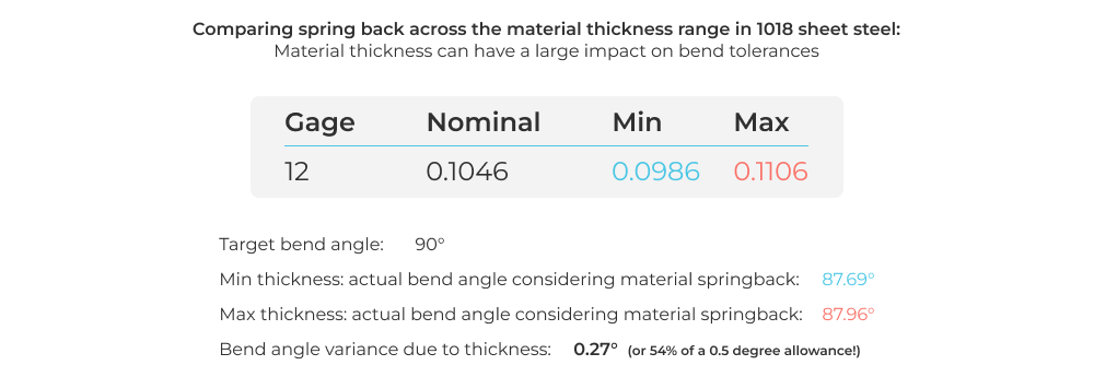
Be sure to consider both material thickness and thickness variability when selecting bend tolerances.
How to make a complete sheet metal drawing
Just like any other part drawing, there are some standard items you will need to include on your sheet metal drawings in order to generate easy to interpret 2D drawings that capture your design intent. We won’t focus on the boilerplate items like title blocks, company information, revision tables etc… If you want a great primer on the basics of engineering drawings check out our Drawings 101 article and the free Five Flute drawing review checklist. The rest of this section will focus on sheet metal specific drawing considerations and best practices.
Sheet metal specific drawing items
Flat pattern views
All drawings need orthographic views to represent 3D geometry generally. In addition to these views, it can be very helpful to include a 2D flat pattern drawing with reference dimensions. This can help your manufacturer consider how the parts will be laid out and nested on sheet stock and how many profiles they can cut per square foot of sheet. Just like providing part surface area to anodizing vendors, the 2D flat pattern can speed up quote turnaround time.
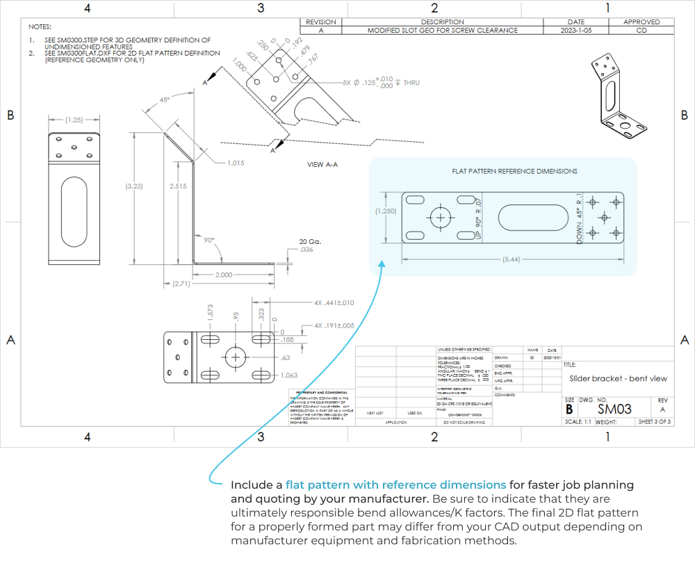
But be careful because it can also cause some confusion. The exact 2D flat pattern geometry that is necessary to create an accurate formed part may differ significantly from your CAD output. Different material stretch behavior (K-factors, bend allowances & spring back), as well as equipment and forming techniques can impact the relationship between 2D and 3D forms. Manufacturers should know that your flat pattern (at best) should be used for reference geometry, and likely may not result in an accurate final part.
Complete, realistic, and properly formatted dimensioning
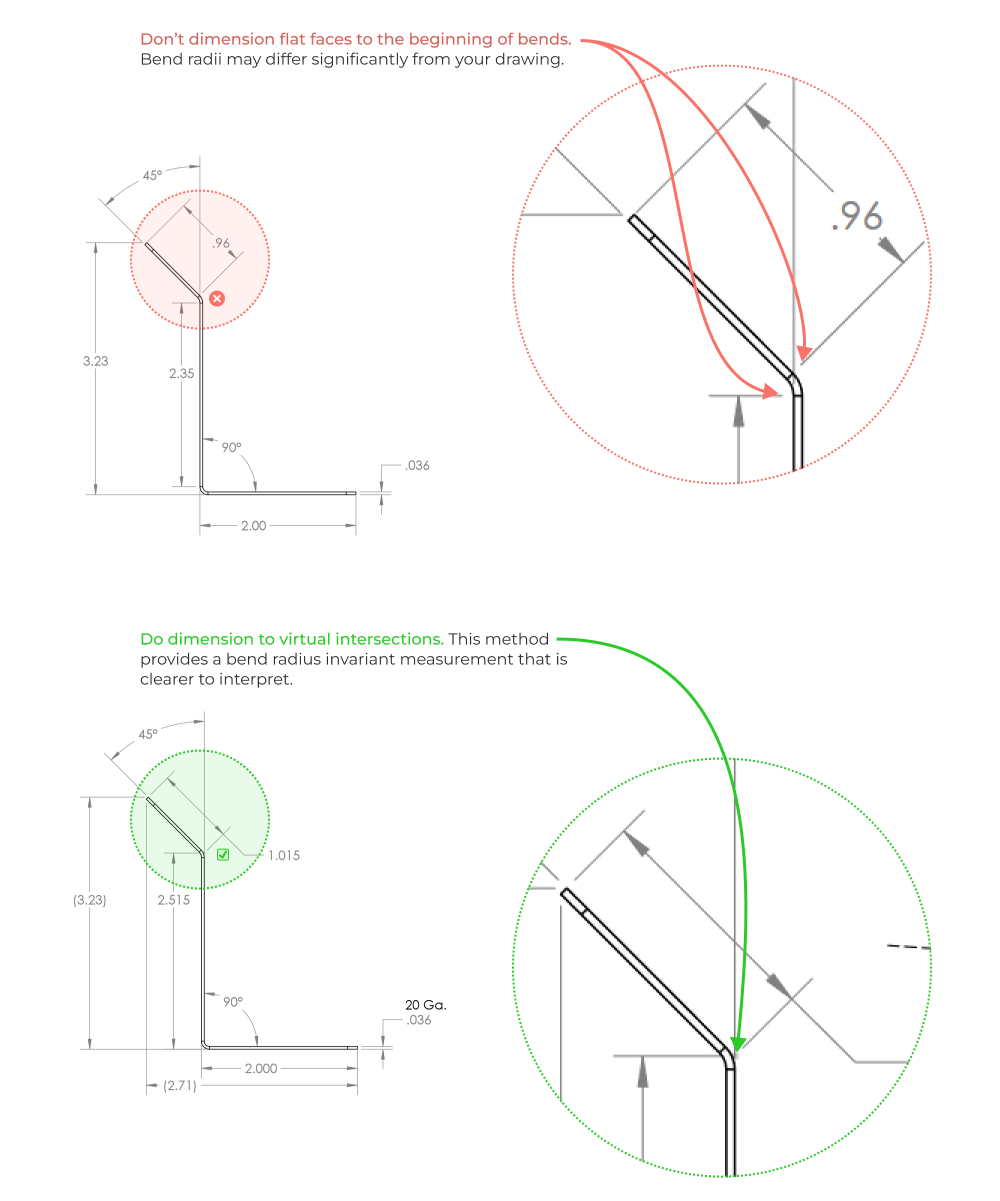
A fully dimensioned sheet metal drawing includes dimensions for all bends, holes, countersinks, flanges, and other formed features (such as hems and curls, ribs, dimples, etc…). It is a best practice to dimension to virtual intersection points and show included bend angles. This ensures that your drawing is universally interpret-able (with no extra math) regardless of the actual bend radius as formed.
Don’t go crazy with GD&T
We write a lot about GD&T, and sheet metal is an area where I see people go wrong consistently. Before applying GD&T to sheet metal drawings, remember that sheet metal components are relatively compliant. This means they conform to the components they are assembled with. If you are specifying tight tolerances of form (straightness and flatness) or tolerances of orientation (parallelism, perpendicularity), first ask yourself, is this even necessary? In the assembled condition, will your tolerances make a meaningful difference to the as build geometry and functionality?
This doesn’t mean you should eschew GD&T entirely however! You can use tolerances of location, like true position, and material condition modifiers (applying position at maximum material condition for example) to develop cost effective flat pattern designs that maintain design intent in the bent configuration.
Include common sheet metal specific information
Don’t forget to add these items to your sheet metal drawings.
- Sheet stock size and preferred suppliers. Stock size thickness tolerance can vary with manufacturer!
- Hardware installation details. If you or your manufacturer are installing additional hardware (PEM nuts, rivet nuts, etc…) make sure you include this on the drawing!
- Finishing information. Finishing information is a must on every drawing, but especially sheet metal parts. Manufacturers often have powder coating booths on site, so be sure to include your powder coat spec on the drawing as well. Note, the less specific you are on part finishes, the less likely you are to receive a high quality finish. It’s incumbent on you to be thorough as far as cosmetics are concerned. This means including things like surface preparation, primers, paint or powder types according to manufacturer designation numbers or other specifications like FS 595C, number of coats, and desired thickness after paint/powdercoat.
File Preparation and Manufacturer Collaboration
Because sheet metal components require multiple manufacturing processes, proper file preparation can speed up both the quoting and production processes. The first step is to speak with your manufacturers and learn what file formats they prefer for each process. This can reduce file conversion workload, which is often a source of mistakes (anyone who has received a 1:2 scaled down set of flat patterns will shudder when they read this).
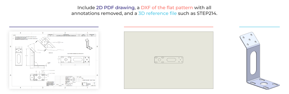
As a general best practice, you should include a fully dimensioned 2D PDF drawing and a reference 3D file type (such as STEP). You may also elect to include a DXF file with the flat pattern only. It can speed up production if you remove all annotations from this view and only include an easily select-able part profile for CAM programming and quoting. The drawing should have a note that explicitly references this file (for revision control purposes). If ordering via a purchase order, you should make note of the filenames on the PO, and update the PO to include proper revision references. You don’t want to be in a position where the manufacturer fulfills the purchase order correctly by ignoring (or missing) the latest revision changes. PDF drawings, immutable CAD/CAM files, and purchase orders need to always stay in sync!
Example Drawings and Files
For the sake of completeness and clarity, we’ve included downloadable example files below that represent a typical set of complete manufacturing output files.
DXF file with boarders, dimensions, and all annotations removed
Create your own drawing checklist
It’s a good practice to build your own manufacturing process specific checklists for your part designs and engineering drawings. Make sure to include the items covered in this article, plus any specifications or design patterns that are common to your designs. If you want a starting point for this checklist in pdf, google sheets, or notion template forms you can check out our free drawing review checklist.
You need a review process
Despite the best intentions of design engineers and drafters designing sheet metal parts, items will be overlooked. In most cases, it helps to run a simple drawing review process or peer check for anything with a modicum of geometric and cosmetic complexity. If you want to put in place a review process that eliminates mistakes, shortens development cycles, and guarantees you’ll design and build better hardware, check out our Ultimate Guide to Drawing Reviews. You’ll learn how to institute a frictionless drawing review process no matter what stage of product development you are working through.
Five Flute - Next generation collaboration for hardware product development
If you are a design engineer or technical project manager and you want to design better products in less time, consider Five Flute. It’s the fastest way to share, review, and improve your engineering designs. From engineering drawing reviews to 3D design reviews of complex parts and assemblies, Five Flute is built for modern engineering teams that want to move faster without making mistakes.
You might also be interested in
Five Flute drawing review checklist
Drawings 101 - The basics of creating high quality engineering drawings
**Mastering GD&T: Material modifiers on data reference frames** (coming soon)